1-18 750-166
CB780/CB784
OPERATION
Operation
SEQUENCE OF OPERATION
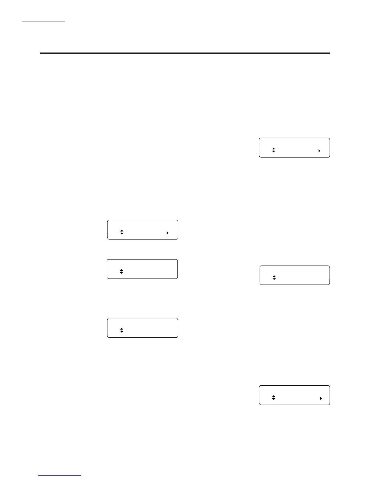
The CB780/CB784 has the following operating sequence,
see Fig. 18 and Table 4.
INITIATE
The CB780/CB784 enters the INITIATE sequence when
the Relay Module is powered. The CB780/CB784 can also
enter the INITIATE sequence if the Relay Module verifies
voltage fluctuations of +10/-15% or frequency fluctuations
of +/-10% during any part of the operating sequence. The
INITIATE sequence lasts for ten seconds unless the voltage
or frequency tolerances are not met. When the tolerances are
not met, a hold condition will be initiated and will be
displayed on the VFD for at least five seconds. When the
tolerances are met, the INITIATE sequence will restart. If
the condition is not corrected and the hold condition exists
for four minutes, the CB780/CB784 will lockout. Causes for
hold conditions in the INITIATE sequence:
a. AC line dropout is detected.
b. AC line frequency error caused by using a 60 Hz device
on a 50 Hz line, or vice versa.
c. AC line noise that can prevent a sufficient reading of
the line voltage inputs.
d. Brownouts caused by a low line voltage.
The INITIATE sequence
also delays the burner motor
starter from being energized
and de-energized from an
intermittent AC line input or control input.
STANDBY
The CB780/CB784 is
ready to start an operating
sequence when the operat-
ing control determines a call for heat is present. The burner
switch, limits, operating control and all microcomputer moni-
tored circuits must be in the correct state for the CB780/
CB784 to continue into the PREPURGE sequence.
NORMAL START-UP
PREPURGE
The CB780/CB784 pro-
vides a PREPURGE timing
selectable from 30 seconds to 2-1/2 minutes with power
applied and the CB780/CB784 operating control indicating
a call for heat:
a. Running Interlocks, Preignition Interlocks, Burner
Switch, Run/Test Switch, Lockout Interlocks and all
microcomputer monitored circuits must be in the cor-
rect operating state.
b. The blower motor output, terminal 5, is powered to
start the PREPURGE sequence. The firing rate motor
is driven to the high fire position. The PREPURGE
timing does not begin until the Lockout Interlock
String and High Fire Switch are both closed.
c. The Preignition Interlock input must remain closed
throughout PREPURGE; otherwise, safety shutdown
occurs.
d. The Lockout Interlock or Running Interlock inputs
(interlock circuit including Airflow Switch) must close
by ten seconds into PREPURGE; otherwise, a safety
shutdown occurs.
e. After the firing rate motor reaches the PREPURGE
rate position and PREPURGE timing is completed, the
firing rate motor will drive to the low fire position.
f. When the firing rate motor reaches low fire position,
the Low Fire Switch, terminal 18, input must be
energized before entering the Ignition Trial state.
IGNITION TRIALS
a. Pilot Flame Establish-
ing Period (PFEP):
1. With the firing
rate motor at the low fire position:
a. The pilot valve and the ignition transformer,
terminals 8, 10 and 21, are energized. The
CB780/CB784 has a fifteen second interrupted
pilot valve, terminal 21 and a ten second inter-
rupted pilot valve/ignition, terminal 8.
b. During PFEP, the Low Fire Switch must remain
closed. If it opens, a safety shutdown occurs.
c. The Preignition Interlock input is ignored
throughout the Ignition Trial state.
2. Flame must be proven by the end of the four or ten
second PFEP to allow the sequence to continue. If
flame is not proven by the end of PFEP, a safety
shutdown occurs.
3. With flame proven, the ignition, terminal 10, is de-
energized for early spark termination.
b. Main Flame Establish-
ing Period (MFEP):
1. The CB780/CB784
has a selectable ten second or fifteen second
MFEP. After the Ignition Trials, and with the pres-
ence of flame, the main fuel valve, terminal 9, is
powered. If a flameout occurs, the CB780/CB784
will lockout within 3 seconds.
RUN
1. A ten second stabilization period occurs at the begin-
ning of the RUN period.
2. The firing rate motor releases to modulation.
3. The CB780/CB784 is now in RUN and will remain in
RUN until the controller input, terminal 6, opens, indicating
that the demand is satisfied or a limit has opened.
POSTPURGE
The CB780/CB784 pro-
vides a fifteen second
POST-PURGE following
the completion of the RUN
period. The blower motor output is powered to drive all
products of combustion and any unburned fuel from the
INITIATE 00:10
Diagnostic Info
STANDBY
Total Cycles 132
PURGE 00:30
Total Hours 396
PILOT IGN 00:10
Fault History
MAIN IGN 00:15
Flame Signal 2.7V
RUN
Expanded Annun.