750-166 1-19
CB780/CB784
OPERATION
combustion chamber. It also supplies combustion air to burn
fuel being purged from the fuel line downstream of the fuel
shutoff valve.
1. The main fuel valve and intermittent pilot valve, termi-
nals 9 and 21, are de-energized and the firing rate motor is
commanded to the low fire position to begin the POSTPURGE
period.
2. The Preignition
Interlock closes within the
first five seconds of
POSTPURGE.
3. After the fifteen second POSTPURGE period is com-
pleted, the CB780/CB784 reenters STANDBY.
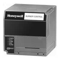
Fig. 18—CB780/CB784 sequence.
CB 780/CB 784
POWER
00
VFD
DISPLAY
OPERATING
CONTROLS
AND
INTERLOCKS
BURNER
FLAME
SIGNAL
FIRING
RATE
MOTOR
INITIATE
POWER
STANDBY
POWER
PREPURGE
DRIVE TO
HIGH FIRE
POWER
PILOT
FLAME
MAIN
POWER
PFEP
4 OR 10 SEC
PILOT
FLAME
MAIN
POWER
MFEP
PILOT
FLAME
MAIN
RUN
POWER
POSTPURGE
POWER
STANDBY
00 00 10 25 00 1520
MOTOR OUTPUT SWITCHING
MOTOR ACTION
BURNER/BLOWER MOTOR
IGN.
15 SEC. PILOT
LIMITS AND BURNER CONTROLLER CLOSED
LOCKOUT INTERLOCKS CLOSED
PREIGNITION INTERLOCK CLOSED
LOW FIRE SW.
SAFE START CHECK
FLAME PROVING
10 SEC. IGN./PILOT
8
10
5
5 SEC.
21
6
TO
7TO
20TO
5
18
TO
13 15
TO
13
12
TO
M7411
INTERLOCK CHECK
HIGH FIRE SW.
19
TO
13
14
TO
13
14
TO
5
4
6
L1
MAIN VALVE
9
TIMED
PURGE
POWER
FLAME
MAIN
PILOT
ALARM
POWER
FLAME
MAIN
PILOT
ALARMALARMALARMALARM
PREPURGE
DRIVE TO
LOW FIRE
00
LED
DISPLAY
IC
PII
SSC
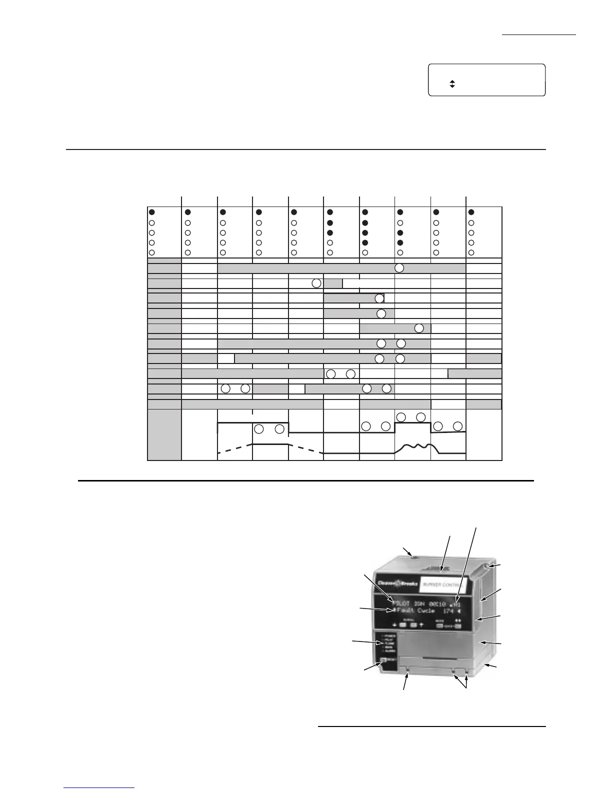
Fig. 19—Keyboard Display Module and
sequence status LEDs (Table 4).
FIVE WIRE CONNECTOR FOR
COMMUNICATIONS, REMOTE
KEYBOARD DISPLAY AND REMOTE RESET
SEQUENCE
STATUS
SELECTABLE
MESSAGE OR
PREEMPTIVE
MESSAGE
SEQUENCE
STATUS
LEDs
RESET
PUSH
BUTTON
FLAME
SIMULATOR INPUT
FLAME CURRENT
TEST JACKS
RUN/TEST SWITCH
DI = DIAGNOSTICS
H1 = HISTORY
EA = EXPANDED
ANNUNCIATOR
CAPTIVE
MOUNTING
SCREW
PLUG-IN
PURGE
CARD
KEYBOARD
DISPLAY
MODULE
RELAY
MODULE
FLAME
AMPLIFIER
M7395
KEYBOARD DISPLAY MODULE (VFD)
The first line of the Vacuum Fluorescent Display (VFD)
provides current status of the burner sequence (STANDBY,
PURGE, PILOT IGN, MAIN IGN, RUN and POST-
PURGE), timing information (PURGE, PILOT IGN, MAIN
IGN and POSTPURGE) in minutes and seconds, hold infor-
mation (PURGE HOLD: T19) and lockout information
(Lockout, Fault Code, Message and Sequence); see Fig. 19.
The extreme right side of the first line will either be blank or
it will show a small arrow pointing to the second line
followed by a two-letter code (DI-Diagnostic Information,
Hn-Fault History Information, and EA-Expanded Annun-
ciator). When the arrow and two-letter code are displayed, it
indicates the second line is showing a selectable message
submenu. The second line will display selectable or preemp-
tive messages. A selectable message supplies information for
flame strength, system status indication, system or self-diag-
nostics and troubleshooting. A preemptive message will have
parentheses around the message and supply a detailed mes-
sage to support the sequence status information. A preemp-
tive message can also be a lockout message. A preemptive
POST PURGE 00:12
Device RM7800L
Flame Signal 0.0V
*
* NOTE: REMOTE RESET MUST BE MOUNTED WITHIN SIGHT
OF THE BOILER CONTROL PANEL.