EXCELLENCE VERSION
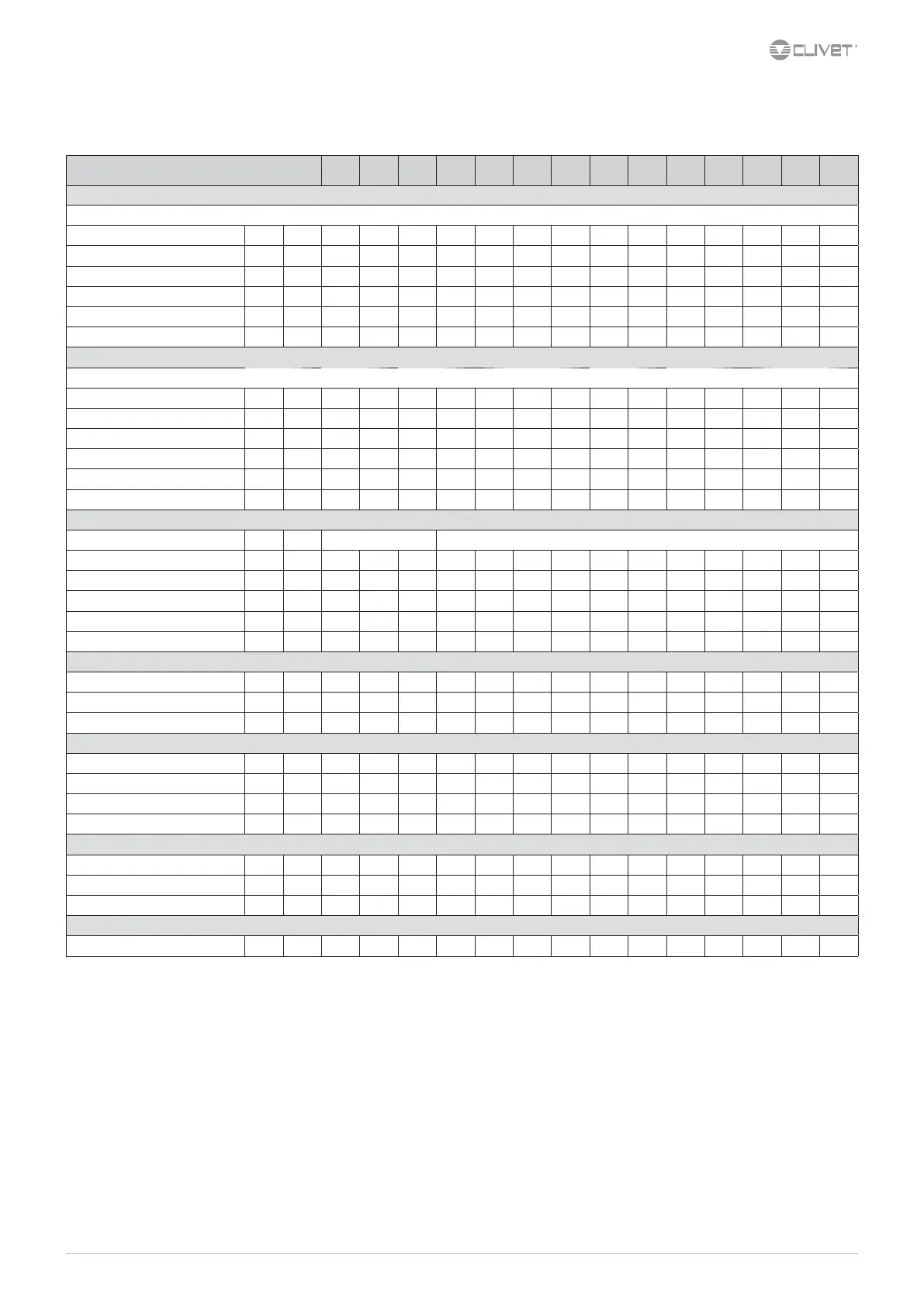
General technical data
Size 21 31 41 51 71 81 91 101 121 131 141 151 161 171
Radiant panels
Cooling
Cooling capacity 1 kW 4,25 6,33 8,06 10,3 13,0 15,9 18,7 20,9 26,5 33,0 39,8 40,5 47,6 52,9
Total power input 2 kW 1,07 1,68 2,10 2,72 3,42 3,87 4,84 5,74 6,27 8,34 9,88 10,3 12,0 13,9
EER (EN 14511:2013) 3 3,97 3,77 3,85 3,80 3,81 4,12 3,86 3,65 4,23 3,96 4,03 3,92 3,97 3,80
ESEER 4 5,86 5,43 5,95 5,09 6,04 6,62 6,86 6,61 7,71 5,77 5,77 5,30 4,98 4,89
Water ow-rate 1 l/s 0,20 0,30 0,39 0,49 0,62 0,76 0,89 1,00 1,27 1,58 1,90 1,94 2,27 2,53
Useful pump discharge head 1 kPa 58 51 43 45 46 64 59 55 69 100 103 101 84 67
ELFORoom and ELFOSpace terminal units
Cooling
Cooling capacity 5 kW 4,40 5,65 8,00 10,2 13,1 15,5 17,4 19,6 25,3 26,8 32,4 36,4
43,2 48,1
Total power input 2 kW 1,58 2,04 2,91 3,78 5,12 5,18 6,26 7,83 8,69 8,56 10,2 12,2 14,4 16,4
EER (EN 14511:2013) 3 2,79 2,77 2,75 2,69 2,55 2,99 2,78 2,50 2,91 3,13 3,18 2,99 3,00 2,93
ESEER 6 4,42 4,09 4,43 4,28 4,76 5,18 5,13 4,90 5,71 4,18 4,27 3,88 3,80 3,75
Water ow-rate 5 l/s 0,21 0,27 0,38 0,49 0,63 0,74 0,83 0,94 1,21 1,28 1,55 1,74 2,06 2,30
Useful pump discharge head 5 kPa 57 53 43 45 45 64 62 58 72 124 122 112 98 83
Compressor
Type of compressors Rotary inverter dc Scroll inverter DC
Refrigerant R-410A R-410A R-410A R-410A R-410A R-410A R-410A R-410A R-410A R-410A R-410A R-410A R-410A R-410A
No. of compressors 11111111111111
Oil charge 0,35 0,35 0,87 1,70 1,70 1,90 1,90 1,90 1,90 1,90 3,30 3,30 3,60 3,60
Refrigeration circuits 11111111111111
Refrigerant Charge 2,1 1,9 2,1 3,3 4,4 4,7 4,7 4,7 6,8 6,8 6,8 10 10 10
User side exchanger
Type of internal exchanger PHE PHE PHE PHE PHE PHE PHE PHE PHE PHE PHE PHE PHE PHE
No. of exchangers 11111111111111
Water content 0,56 0,64 0,64 1,14 1,80 2,37 2,37 2,37 3,13 3,13 3,13 3,13 4,27 4,27
External Section Fans
Type of fans AX AX AX AX AX EC EC EC EC EC EC EC EC EC
No. of fans 11122111211111
Standard airow 653 1028 1028 2081 1996 2222 2306 2444 2778 4694 4694 5139 5649 5833
Installed unit power 0,12 0,15 0,15 0,15 0,15 0,19 0,23 0,27 0,20 0,63 0,63
1,03 1,02 1,36
Water circuit
Maximum water side pressure 550 550 550 550 550 550 550 550 550 550 550 550 550 550
Safety valve calibration 600 600 600 600 600 600 600 600 600 600 600 600 600 600
Min. installation water contents 17 20 25 33 40 50 53 57 63 68 87 99 113 117
Power supply
Standard power supply
230/1/50 230/1/50 230/1/50 400/3/50+N 400/3/50+N 400/3/50+N 400/3/50+N 400/3/50+N 400/3/50+N 400/3/50+N 400/3/50+N 400/3/50+N 400/3/50+N 400/3/50+N
1. Entering/leaving water temperature user side 23/18°C, external exchanger entering air 35°C
2. The overall power absorbed is calculated by adding the power absorbed by the compressor + the power absorbed by the fan - the percentage value of the fan to overcome external pressure drop + the power absorbed by the pump - the percentage value of the pump to
overcome pressure drop outside + the power absorbed by the auxiliary electrical circuit
3. EER (EN 14511:2013) cooling performance coecient. Ratio between delivered cooling capacity and power input in compliance with EN 14511:2013
4. ESEER calculated by Clivet for radiant systems with water produced at 18°C by taking into account the load conditions and source water temperature as dened by EUROVENT for water at 7°C
5. User side entering/leaving water temperature 12/7 °C, external exchanger entering air 35°C
6. ESEER calculated by EUROVENT, for systems featuring terminal units with water produced at 7°C
7. PHE = plate exchanger
8. AX = axial-ow fan, EC = axial-ow fan + EC
The heads are intended as available at the unit connections
The pressure drops of the steel mesh strainer, supplied with the unit, have been already taken into consideration
 Loading...