24 Series Installation and User Guide V1.0
10
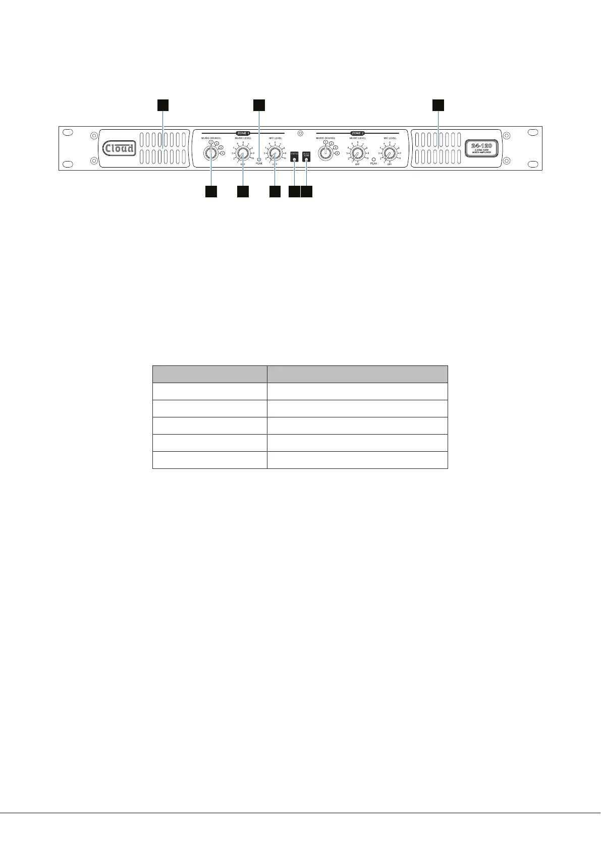
Front panel description
4 77
1 562 3
24-120 front panel: 24-240 is functionally identical.
1. MIC LEVEL – per-zone level controls for the Mic Input.
2. MUSIC SOURCE – per-zone selection of active Line Input (1 to 4).
3. MUSIC LEVEL – adjusts level of selected Line Input in each zone.
4. PEAK – per-zone red LED: illuminates if either Mic or Line signal levels are high enough to activate the zone’s output limiter.
5. MUSIC MUTE – red LED: illuminates when external Music Mute is active.
6. STATUS – bicolour LED indicates as follows:
INDICATION MEANING
Off
Power off
Green
Normal operating mode
Red
Standby (APD) mode
Flashing green
Power reduction due to high temperature
Flashing red
Fault condition - outputs muted
7. Forced air cooling intake slots – do not block.