24 Series Installation and User Guide V1.0
19
Facility Port
24 Series mixer-ampliers are provided with a FACILITY PORT
in the form of a rear panel RJ45 connector [18]. The primary
use of the Facility Port is for the connection of remote active
modules such as the LM-2 or BT-1, but it may also be used
as a general-purpose auxiliary balanced input (see page 22
for more information on this application). The Facility Port
audio path includes a noise gate to help minimise unwanted
background noise from the external source.
If Mic-over-Music priority is enabled (see “Paging control
and mic priority” on page page 16), an input at the Facility
Port will be reduced in level by 25 dB in the same way as the
other Line Inputs, though this may be overridden by moving
internal jumper J4 from its default setting (DIS) to EN. See
page 25 for locations of PCB jumpers.
An audio source connected to an active module will be
routed via the Facility Port to Zone 1 by default, and the
music source currently selected for Zone 1 will be muted and
replaced by the Facility Port audio. The Facility Port routing
may be altered by moving internal PCB jumper J3 from Z1 to
ALL: in this setting, audio sources connected to remote active
modules will be routed to both zones.
The remote control functions of an LM-2 (music source and
level) will affect only the music signal routed to Zone 1.
However, note that if J3 is set to ALL, the remote control
functions of an LM-2 module will be disabled (see also below).
IMPORTANT: In order for the remote control
functions on an LM-2 module to operate
(with J3 in the default Z1 setting), the rear
panel Z1 LOCAL/REMOTE button must be set
to REMOTE (button IN). This will disable the front panel
MUSIC SOURCE and MUSIC LEVEL controls, and control
of music level and/or source selection will be available
from the remote module. The Z1 LOCAL/REMOTE button
should be left set to LOCAL (button OUT) when a BT-1,
L-1 or M-1 module is connected to the Facility Port.
IMPORTANT: do not connect BOTH an LM-2
module (or an RSL plate connected via a BT-1
module) to the Facility Port AND an RL or RSL
Series plate to the Zone 1 REMOTE connector,
as the remote controls will conict.
IMPORTANT: if jumper J3 is set to ALL,
remote music source and level control via the
Facility Port is disabled: in this case, set the
Z1 LOCAL/REMOTE button to REMOTE only if
the Z1 REMOTE port is in use, and to LOCAL otherwise.
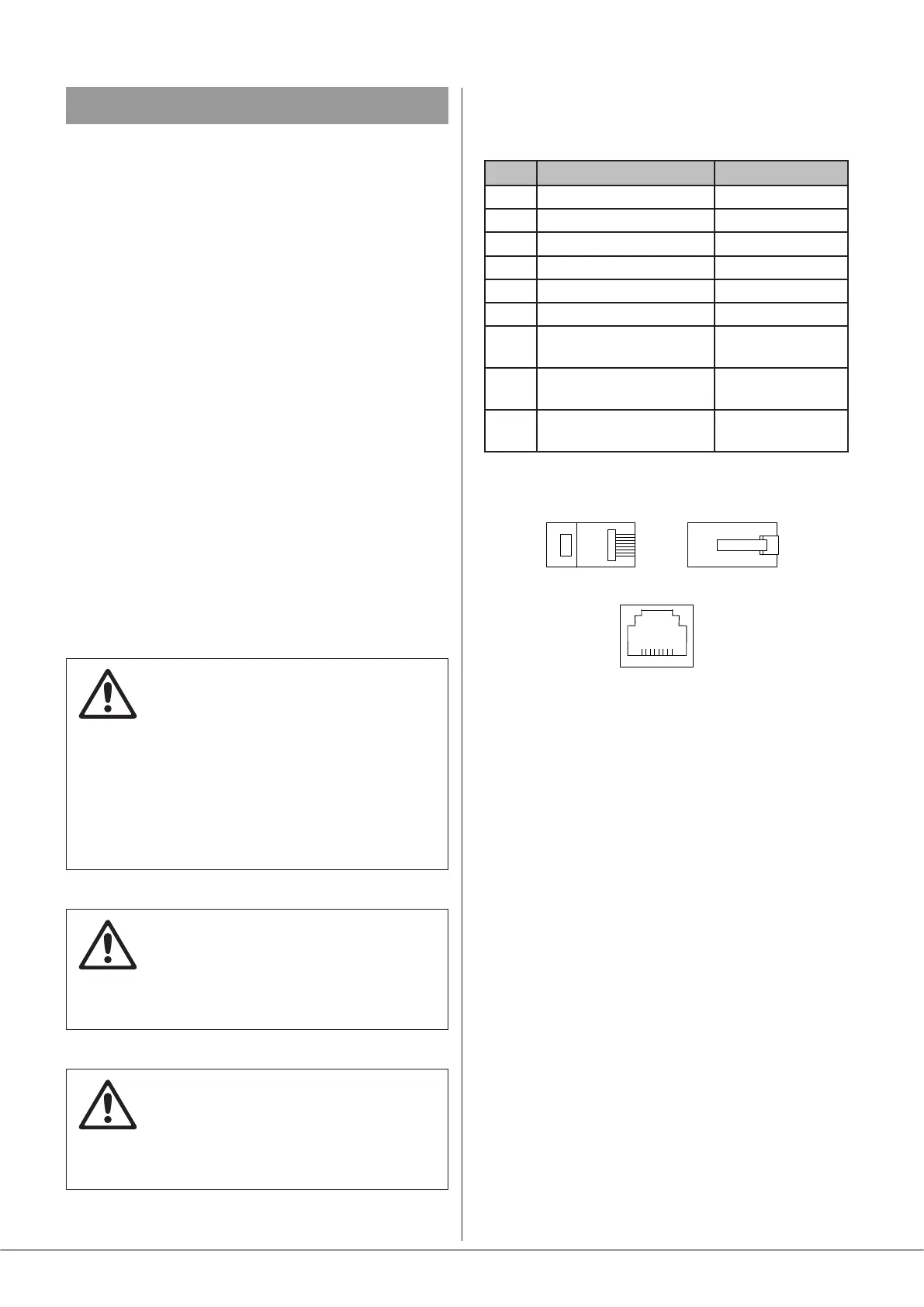
The pinout of the Facility Port connector is given in the table
below:
PIN USE Cat 5 CORE*
1 Audio ‘cold’ phase (-) White + Orange
2 Audio ‘hot’ phase (+) Orange
3 Priority VCA control White + Green
4 + 12 V Blue
5 0 V White + Blue
6 -12 V Green
7 Music level control
(0 to 10 V)
White + Brown
8 Music source select
control (0 to 10 V)
Brown
SCN GND ref for system
music controls
Connector shell
* Standard wiring for pre-made cables
The various optional Cloud remote active modules operate
from DC power supplied by the 24 Series mixer-amplier.
The current consumed by each module is minimal and in the
vast majority of installations there will be no power supply
issues.