24 Series Installation and User Guide V1.0
11
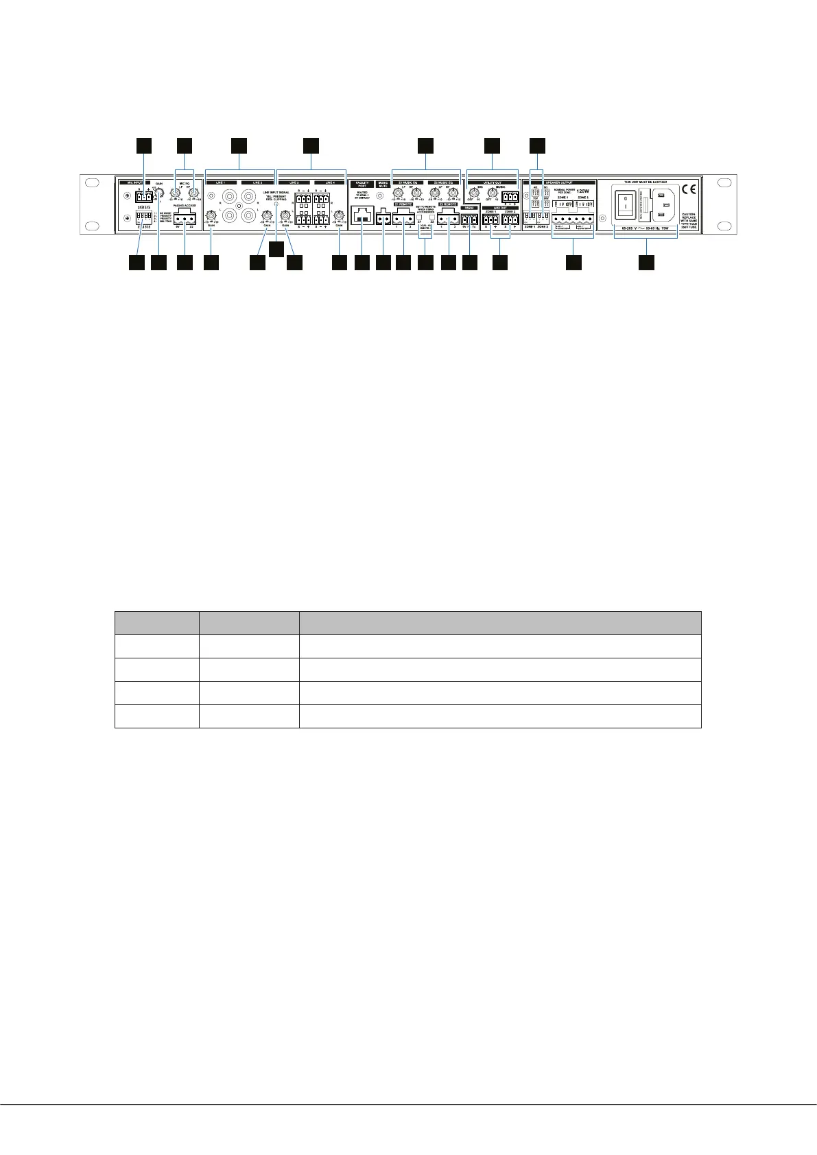
Rear panel description
813
1017 1514
11
10 10 10 18 26 19 19 21
16 2324
20 25 22 27
9 12
24-120 rear panel: 24-240 is functionally identical.
8. LINE 1 and LINE 2 – unbalanced stereo line inputs for music sources.
9. LINE 3 and LINE 4 – balanced stereo line inputs for music sources.
10. GAIN 1 to GAIN 4 – level trims for each line input.
11. LINE INPUT SIGNAL – bicolour LED; illuminates yellow when an input signal is detected at any of the line inputs, and red
if any input signal exceeds clip level.
12. Z1 and Z2 MUSIC EQ – LF and HF EQ adjustment of music channel for each zone.
13. MIC INPUT – balanced input for microphone.
14. GAIN – level trim for mic input.
15. PAGING ACCESS – external paging control port.
16. MIC EQ – LF and HF EQ adjustment for microphone.
17. 4-pole DIP switch for conguring paging operation:
SWITCH NAME FUNCTION
SW1
PAGE MODE
MIC 1 mode – congures the mic input for paging use
SW2
Z1 PRIORITY
Enables mic-over-music priority in Zone 1
SW3
Z2 PRIORITY
Enables mic-over-music priority in Zone 2
SW4
CHIME TONE
Enables pre-announcement chime tone in both zones
18. FACILITY PORT – RJ45 socket for connection of remote active input/control modules such as the LM-2, BT-1, L-1 and
M-1. This port may alternatively be used as an additional balanced line input. Signals applied here are routed to Zone 1 by
default, but may be routed to both zones by moving an internal jumper.
19. Z1 and Z2 REMOTE – for connection of RL-1 or RSL-4/RSL-6 remote control plates.
20. Z1 and Z2 Local/Remote switches – press to enable the corresponding REMOTE port and the remote control functions of
the Facility Port: disables front panel music controls.
21. RS232 – bi-directional RS-232 interface: accepts commands to select or adjust various unit functions and parameters from
an external AV control system.
22. SPEAKER OUTPUTS for each zone – connect to either low-Z loudspeakers (4 or 8 ohms) or to 70/100 V-line distribution
system.