24 Series Installation and User Guide V1.0
22
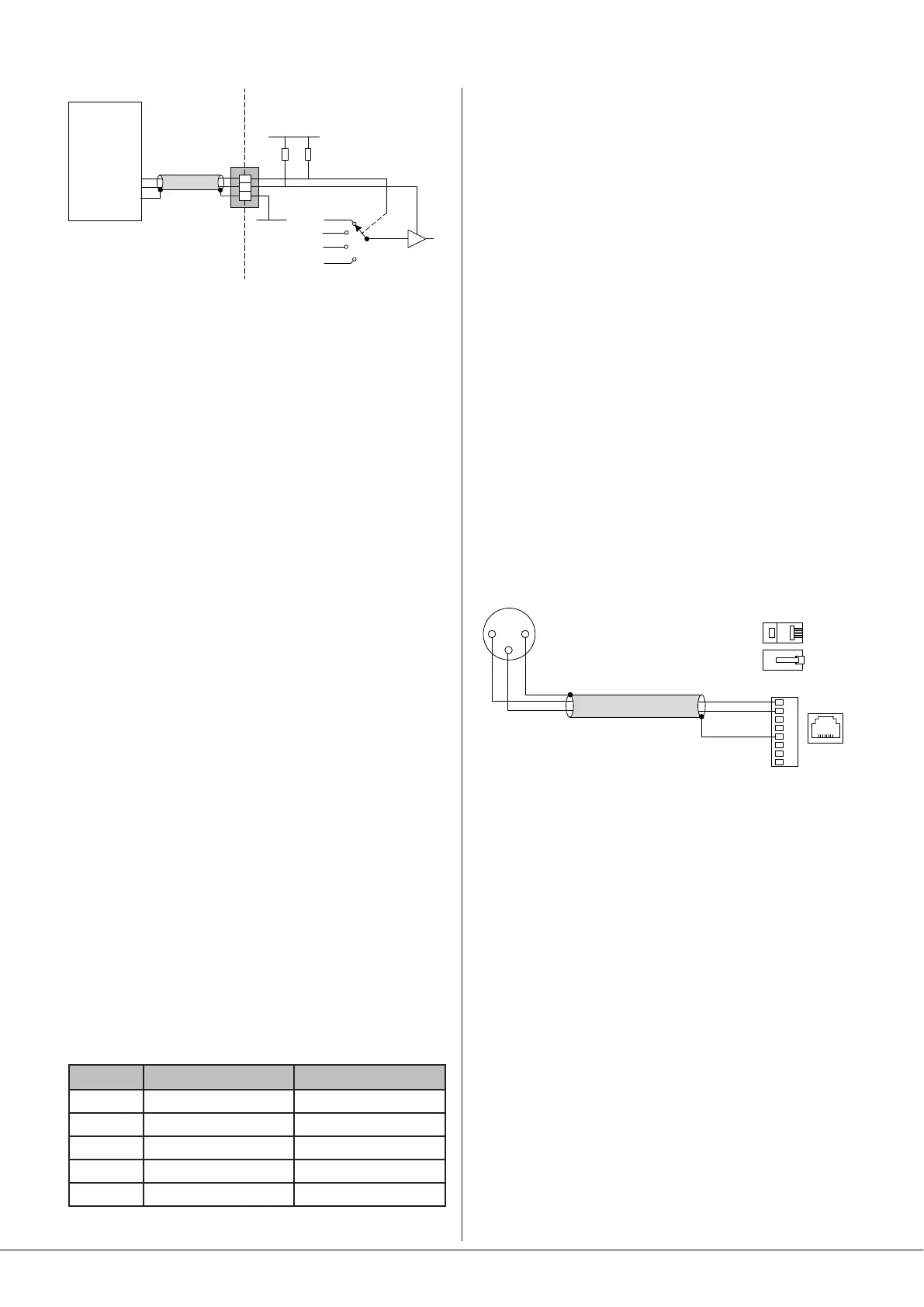
REMOTE
SOURCE+LEVEL
PORT
1
2
3
+3V3
0 V
1k
4k7
CONTROL
SYSTEM
0 V REF
LEVEL CONTROL
SOURCE CONTROL
MUSIC VCA
MUSIC SOURCE
24 Series
NOTE: If the control voltage source is not isolated from the
power earth, there is a small risk of creating a ‘ground loop’
by linking the mixer technical ground (0 V) to the ground
(0 V) of the equipment supplying the control voltages. To
minimise this risk, we suggest that all pieces of equipment be
in close proximity, and supplied from the same power outlet.
Music level
Music level in a zone may be varied over its full range by
applying a DC voltage of between 0 V and +3.0 V to pin 2,
the 0 V reference being connected to Pin 1. 0 V on pin 2
corresponds to maximum level and +3.0 V will produce 90
dB of attenuation. The rate of attenuation is approximately
33 mV/dB.
Note that there is an internal 1k “pull-up” resistor between
pin 2 and the internal +3.3 V rail. If pin 2 is left “oating”, this
pull-up will result in full attenuation. The output impedance
of the control voltage source should be low enough to
overcome the effect of this resistor.
Music source
Music source for a zone may be controlled by applying
various DC voltages of between 0 and +3.3 V to pin 3,
the 0 V reference being connected to pin 1. A voltage of
+1.8 V or less at pin 3 will select Line input 4 and one of 3 V
will select Line input 1. The other line inputs will be selected
with intermediate voltages. Taking pin 3 above +3 V will
deselect all inputs, making the zone effectively ‘off’ for music.
The table below lists the DC voltages required at pin 3 to
select each line input. The third column is the value of a
resistor which should be connected between pins 1 and
3 to permanently ‘force’ a zone to a particular line input.
Note that the values in the table are only correct when PCB
jumpers J6 and/or J8 are in the default RSL-4 position.
INPUT DC VOLTAGE RESISTOR VALUE
OFF >+3.2 V Open-circuit
Line 1 +1.95 V 6k8
Line 2 +1.5 V 3k9
Line 3 +0.9 V 1k8
Line 4 0 V Short-circuit
Note that there is an internal 4k7 “pull-up” resistor between
pin 3 and the internal +3.3 V rail. If pin 3 is left “oating”, this
pull-up will cause ‘OFF’ to be selected. The output impedance
of the control voltage source should be low enough to
overcome the effect of this resistor.
Using the Facility Port as an
auxiliary input
The Facility Port can route an audio source to either Zone 1,
or to both zones, depending on the setting of internal PCB
jumper J3. If the port is not connected to a remote input
module it can be used as an additional, balanced line input.
The signal applied at the Facility Port is mixed with the other
music inputs but is NOT affected by the rear panel MUSIC
EQ controls [12]. The Facility Port signal has no independent
level control; level should be adjusted at the source. If Mic-
over-Music priority is enabled (see “Paging control and mic
priority” on page page 16), a line input at the Facility Port
will be reduced in level by 25 dB in the same way as the
other Line Inputs, though this may be overridden by moving
internal jumper J4 from its default setting (ON) to OFF. See
page 25 for locations of PCB jumpers.
Connect an external balanced source to the Facility Port as
shown below:
FACILITY PORT (RJ45)
1
3
2
BALANCED
OUTPUT (e.g., XLR)
hot (+)
hot (+)
cold (-)
cold (-)
Twin-core screened cable
1
2
3
4
5
6
7
8
An unbalanced source may also be connected; the use of
balancing transformers is recommended.