24 Series Installation and User Guide V1.0
13
INSTALLATION
Hardware considerations
The 24 Series mixer-amplier is built in a 1U-high 19” rack
mount enclosure. It is recommended that it is installed in a
19” rack wherever possible. Model 24-120 is 150 mm deep,
and Model 24-240 is 230 mm deep: it is recommended that
at least 100 mm of additional rack depth should be available
to allow for rear connectors and cabling.
The choice of installation location will be dictated by the
specics of the system and building layout. It is recommended
that wherever possible, the mixer-amplier should be
mounted adjacent to as many of the music sources (CD
players, music servers, TV receiver boxes, etc.) as practical.
When deciding the mixer-amplier’s location, bear in mind
that access to it (particularly the rear panel) will probably
be required even if a full complement of remote controls is
being tted as part of the system, as certain adjustments can
only be made on the unit itself.
Ventilation
24 Series mixer-ampliers use both convection and forced-
air cooling: at 45°C the internal fan is activated at low speed,
it switches to high speed if the temperature exceeds 60°C.
In both models, air is taken in through two sets of ventilation
slots in the front panels and exhausted through a single set in
the right-hand side panel (as viewed from the front): ensure
that all these are kept unobstructed by cabling or any other
items. It is recommended that a 1U blank panel is tted
above the mixer-amplier to aid heat dissipation; slotted
panels are not recommended as they defeat the action of
forced-air cooling.
24 Series mixer ampliers have been designed to operate in an
ambient temperature range of 0°C to 35°C. While satisfactory
operation outside of this recommended temperature range
may be achievable in a particular installation, no guarantee
can be given regarding full adherence to the performance
specications (see the Appendix section of this manual).
Installers should always endeavour to t the mixer-amplier
in a location where the recommended temperature range
is not exceeded. To help achieve this, we recommend that
the unit is not rack-mounted immediately above other
equipment which generates heat (e.g., older designs of power
amplier).
If the unit is to be used free-standing (i.e., not mounted in
a rack), the push-rivet plastic feet supplied in the accessory
pack should be tted to the bottom of the enclosure.
Power Supply
24 Series mixer-ampliers have an internal power supply of
the “universal” type, and will operate on all AC mains supplies
of between 85 V and 265 V, 45 to 65 Hz. An IEC mains cable
with a plug appropriate for each country is supplied with the
unit. The units are very energy-efcient and consume less
than 6 W in Idle mode; see the Technical Specications on
page 28 for more details.
Fuses and ratings
The only externally-accessible fuse is the AC mains
fuse integral with the IEC receptacle on the rear panel.
Only replace a fuse with one of exactly the same type.
The IEC receptacle has space for a spare fuse; one is supplied
with the unit.
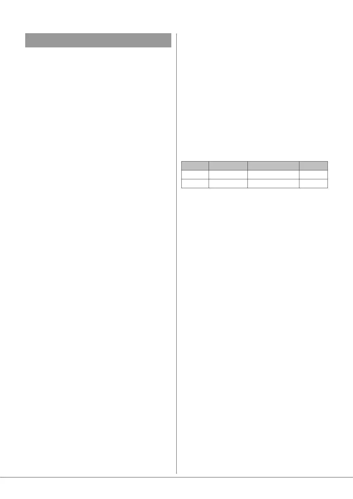
The table below gives the correct fuse type:
Model Fuse Type Fuse size Rating
24-120 T4AH 250V 20 mm x 5 mm 4 A
24-240 T5AH 250V 20 mm x 5 mm 5 A
If a replacement fuse blows immediately, it indicates that
the mixer-amplier has developed a fault, which should be
referred to competent service personnel.
Internally, a 20 mm x 5 mm 2.5 A time-delay fuse protects
each power supply module (one in Model 24-120, two in
Model 24-240). This is a service component, and should
not require attention. Failure of this fuse indicates a fault
condition, which should be immediately referred to a
competent technician or authorised service centre.