24 Series Installation and User Guide V1.0
12
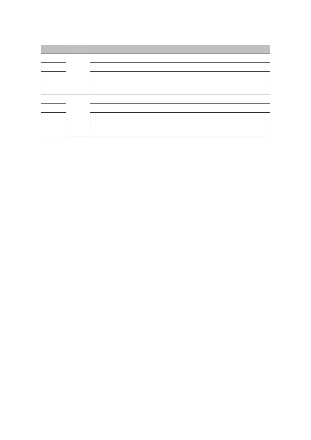
23. Speaker settings – two 3-pole DIP switches for setting output conguration independently in each zone:
SWITCH ZONE FUNCTION
SW1
ZONE 1
Enables Z1 65 Hz high-pass lter (use with 70/100 V-line operation)
SW2 Congures Z1 output for low-Z (ON) or high-Z (70/100 V-line) operation (OFF)
SW3
When SW2 is set ON, selects Z1 output impedance to suit 4 ohm or 8 ohm
loudspeakers
When SW2 is set OFF, selects 70 V-line or 100 V-line operation for Z1
SW4
ZONE 2
Enables Z2 65 Hz high-pass lter (use with 70/100 V-line operation)
SW5 Congures Z2 output for low-Z (ON) or high-Z (70/100 V-line) operation (OFF)
SW6
When SW5 is set ON, selects Z2 output impedance to suit 4 ohm or 8 ohm
loudspeakers
When SW5 is set OFF, selects 70 V-line or 100 V-line operation for Z2
24. UTILITY OUTPUT – a balanced output with an independent mic/music mix: the music source can be set by internal
jumpers. Suitable for use with loop ampliers. The output has two associated preset level controls, MIC and MUSIC.
25. AUXILIARY OUTPUT – per-zone balanced line level outputs for feeding additional ampliers, etc.
26. MUSIC MUTE – Emergency control input for muting music.
27. IEC mains input with mains switch and integral fuseholder.