24 Series Installation and User Guide V1.0
17
Outputs
Speaker Outputs
The power amplier stages are fully protected against DC
offset and output over-current, and also has two-stage
thermal protection. Activation of the protection circuitry
mutes the power amplier stage until the fault condition
clears. All protection conditions will automatically self-
clear once the fault condition is removed, or if the amplier
is power-cycled. The exception to this is muting due to
detection of DC at the output terminals, which will require
manual power-cycling to clear. A switch-on delay function
mutes the output during power-up and power-down to
protect loudspeakers.
Each zone of a 24 Series mixer-amplier has both a low
impedance output (4 or 8 ohms) and a high voltage output
for 70/100 V-line speaker systems. Both output types are
available on the two 3-pin 5 mm-pitch screw-terminal
SPEAKER OUTPUT connectors [22]. The two zones may be
congured independently, but in each zone, only one of the
two output options can be used at a time.
The output type is selected with SPEAKER SETTINGS DIP
switch [23]: see details below
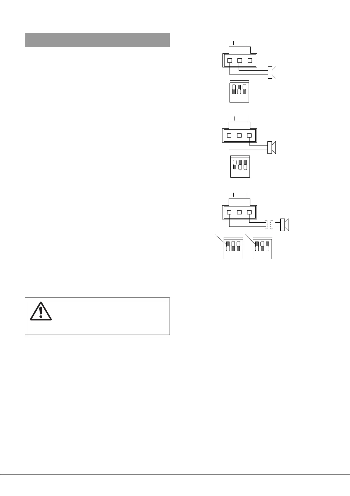
Connecting to Lo-Z loudspeakers
For low-impedance operation, set SW2 to LO-Z (switch
down). The mixer-amplier can deliver its rated power into a
4 ohm or 8 ohm load: set SW3 up (4 ohms) or down (8 ohms)
as appropriate. Installers tting multiple low-impedance
loudspeakers (generally 8 ohms) should employ series and
parallel wiring to produce, where possible, a total load
impedance of either 4 or 8 ohms.
IMPORTANT: Under no circumstances should
the total load impedance be less than the
output impedance selected with SW3 (i.e., 4
or 8 ohms).
For low-impedance operation, wire the SPEAKER OUTPUT
connector according to (a) or (b) in the diagram below.
Connecting to 70/100 V-line systems
Series 24 mixer-ampliers’ output stages use a transformerless
design which can directly drive 70 V-line or 100 V-line
loudspeaker systems. The power amplier stage is rated at
120 W per-zone (Model 24-120) or 240 W per zone (Model
24-240).
Connect to a 70 V-line or 100 V-line speaker system by
setting SW2 to high-Z (switch up) and setting SW3 either up
for 70 V-line operation, or down for 100 V-line operation, as
required: see (c) in the diagram below. Note that units will be
factory-set to 100 V “out of the box”.
4 ohm
loudspeaker
+
-
+
-
70 V-line or
100 V-line
speaker system
(a) Lo-Z (4 ohm)
connection
(c) Hi-Z
connection
COM
4Ω
8Ω /
HIZ
COM
4Ω
8Ω /
HIZ
8 ohm
loudspeaker
+
-
(b) Lo-Z (8 ohm)
connection
COM
4Ω
8Ω /
HIZ
70 V-line
100 V-line
OPTIONAL
OPTIONAL
OR
1 2 3
ON
1 2 3
ON
1 2 3
ON
1 2 3
ON
OR
When driving 70/100 V-line loudspeaker systems there is
a risk of transformer core saturation at high levels and low
frequencies, which can produce distortion. To prevent this,
the mixer-amplier’s output stages is provided with a 65 Hz
high-pass lter, which may be enabled by setting SPEAKER
SETTINGS switch SW1 to on (switch down).
Power Sharing (Model 24-120 only)
Model 24-120 incorporates the principle of Power Sharing
when both outputs are congured for Hi-Z mode (i.e.,
for 70/100 V-line operation). Its maximum power output
capability is 240 W. Each amplier channel (zone output)
is capable of delivering 240 W, but this gure can only be
realised if the other zone output is unused.
Power Sharing is congured by adjusting the power tapping
(wattage setting) on all 70 V-line or 100 V-line speakers. In
each zone, the tappings should be set to give the required
total wattage (eg. Zone 1: 40 W total, Zone 2: 200 W total).
The power sharing between zones can be any ratio so long
as the total wattage for both zones does not exceed 240 W.
The great advantage of power sharing is that it allows
installers to use one zone output to drive speakers where
only low power is needed, and the other for areas where
more is needed.