24 Series Installation and User Guide V1.0
23
24 SERIES SERIAL CONTROL
24 Series mixer-ampliers are equipped with a bi-directional
RS-232 serial interface.
As a receiver, the interface permits external control of many
mixer-amplier settings. These include:
• Music Source selection in each zone
• Music level control in each zone
• Mic level control in each zone
• Mic muting in each zone
Note that the rear panel Remote/Local switches ([20] at page
11) must be set to Remote to enable RS-232 control.
The mixer-amplier appears as a DCE (Data Communications
Equipment) device to controlling equipment. As the
controlling device will probably be congured as a DTE device,
this requires the use of a straight (uncrossed) cable with the
Tx (Data Transmit) pins at the cable ends connected to each
other and the Rx pins (Data Receive) similarly connected to
each other.
The full RS-232 protocol is beyond the scope of this manual,
but is available for download from www.cloud.co.uk. This
section provides only serial port details and an abridged serial
command list.
Port parameters:
Parameter VALUE/SETTING
Data type: RS-232 serial
Data speed 9600 baud*
Word length 8 bits
Parity None
Stop bits One
*The default baud rate of 9600 baud may be altered by sending the
appropriate RS-232 commands; details are in the RS-232 protocol document.
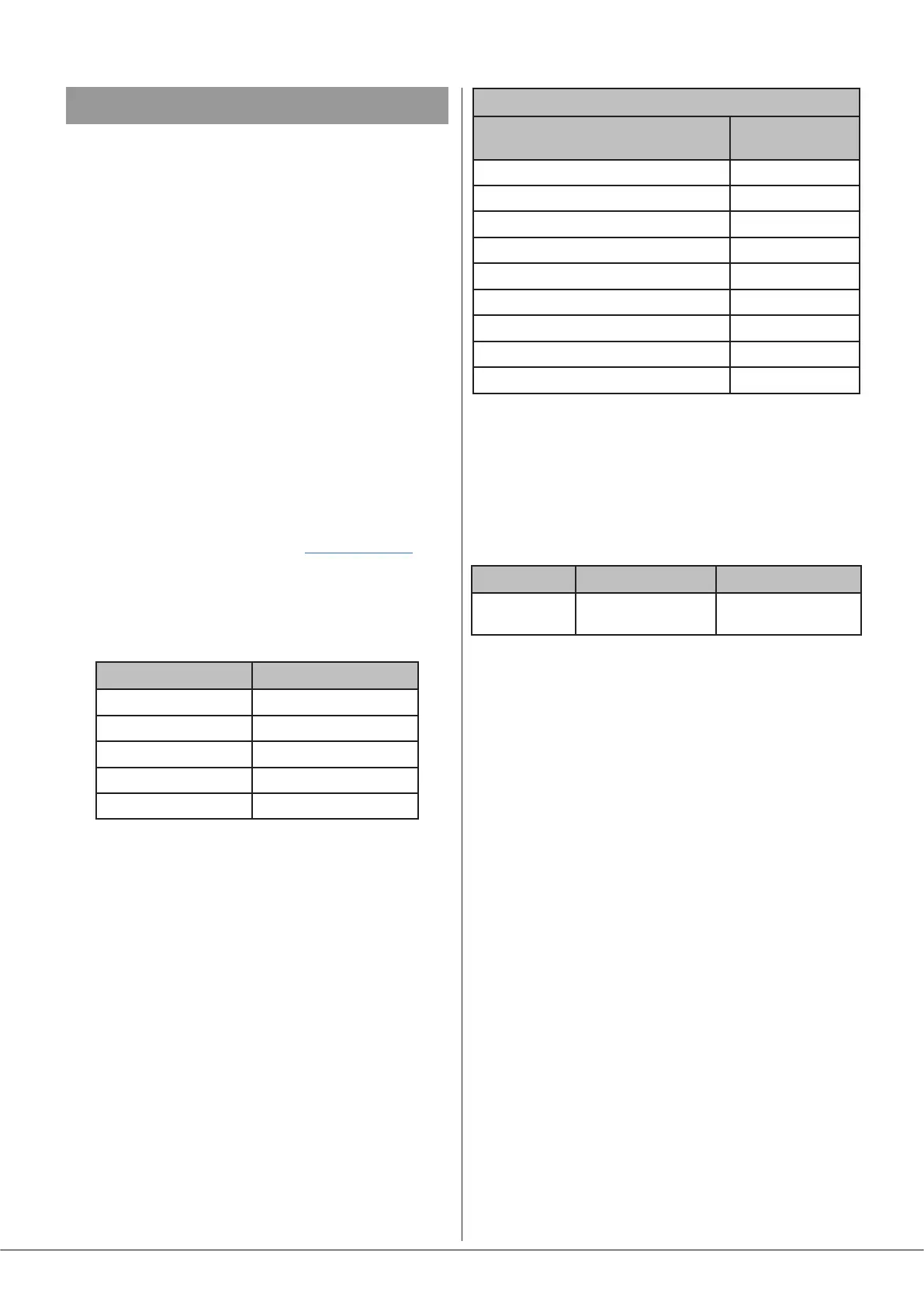
Abridged command set
The commands listed in the table below are some of those
most commonly required when controlling a 24 Series mixer-
amplier from an AV control system. For all other commands,
data requests and responses, please refer to the 24 Series’ full
RS-232 protocol document.
GENERAL FORMAT
FUNCTION COMMAND
(ASCII)
Route Line Input x to Zone y
<Zy.MU,Sx/>
Set music level in Zone y to –m dB
<Zy.MU,Lm/>
Reduce music level in Zone y by p dB
<Zy.MU,LDp/>
Increase music level in Zone y by q dB
<Zy.MU,LUq/>
Mute mic input for Zone y
<Zy.M1,M/>
Unmute Mic input for Zone y
<Zy.M1,O/>
Set mic level in Zone y to –m dB
<Zy.MI,Lm/>
Reduce mic level in Zone y by p dB
<Zy.MI,LDp/>
Increase mic level in Zone y by q dB
<Zy.MI,LUq/>
Examples
1. Music source selection:
The values of x and y in the general format are the Line Input
No. (1 to 4) and the Zone No. (1 or 2) respectively.
EXAMPLE COMMAND (ASCII) COMMAND (HEX)
Select Input 3
in Zone 2
<Z2.MU,S3/>
3C 5A 32 2E 4D 55
2C 53 33 2F 3E
2. Music levels:
Levels can either be set in a specied zone to an absolute
value (in dBs), or increased/decreased by a specied number
of dBs. Either may be dened in steps of 1 dB.
For absolute levels, the number of dBs corresponds to
attenuation rather than gain, thus 0 dB is maximum level and
at -90 dB the zone is muted. The values of y in the general
format is the Zone No. (1 or 2) and m is the attenuation level
in one-dB steps (0 to 90) respectively.
To alter the zone level by a specied amount, the additional
ASCII characters ‘U’ (up) or ‘D’ (down) are added to the string.
The values of y, p and q in the general format are the Zone
No. (1 or 2), the level increase in one-dB steps (0 to 90), or
the level decrease in one-dB steps (0 to 90) respectively. A
command to increment the level by a number of dBs greater
than the current attenuation will set the level to maximum.
Similarly, a command that would decrement the level below
90 dB attenuation will mute the Zone output.