24 Series Installation and User Guide V1.0
14
Connections and Controls
Music Inputs
The unit has four stereo line inputs; these inputs are suitable
for most music sources such as compact disc players, music
servers, laptops, satellite receivers and the like. Each stereo
input is summed internally to mono.
Two inputs – LINE 1 and LINE 2 - are unbalanced, and use
standard phono sockets (RCA jacks) in pairs. LINE 3 and
LINE 4 are balanced, and use pairs of 3-pin 3.5 mm-pitch
screw terminal connectors. The input impedance for all line
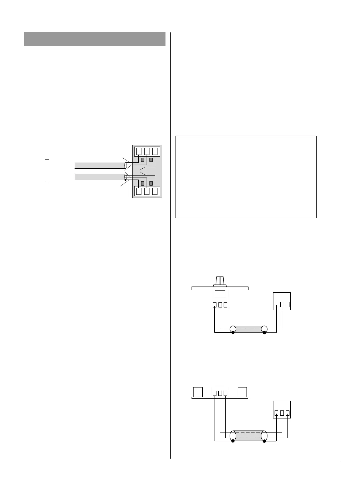
inputs is greater than 10 kohms. Connection to the balanced
inputs should be as shown below:
S
_
+
LEFT CHANNEL
RIGHT CHANNEL
AUDIO
SOURCE
S
_
+
R
L
screen
‘cold’
‘hot’
screen
LINE 4 input can be congured to have automatic priority
over the other music sources: see Music Priority, page 15
Sensitivity & Gain Control
All four stereo line inputs have a preset GAIN control on
the rear panel adjacent to the respective input sockets. The
control has a range of 20 dB allowing the input sensitivity to
be varied from -12 dBu (195 mV) to +8 dBu (2.0 V).
The GAIN control should be adjusted so that all the input
sources are operating at approximately the same volume,
and that the front panel MUSIC LEVEL controls have a useful
range of control.
The rear panel is tted with a bicolour LINE INPUT SIGNAL
LED ([11] at page 11), which is a useful aid to system set-
up. It conrms both that a music source signal is present at
the unit inputs and that all available sources are of a correct
level. The LED illuminates yellow if a signal is present at any
of the line inputs: note that the signal detection is post the
rear panel GAIN controls, but pre the music EQ and level
controls. The LED’s threshold level is -30 dBu with the rear
panel GAIN control set to 0 dB. GAIN should be set so that
the LED never turns red under any circumstances, as this will
indicate an overload level at the power stage inputs, and very
harsh clipping will result.
Music Source Select
Each of the two zones has a front panel MUSIC SOURCE
rotary switch, used to select the desired music signal for the
zone. Remote control of source selection is possible with a
remote control plate (RSL-4/RSL-6), or active input/remote
control module (LM-2), see below and page 19 respectively.
Music Level Control
Two front panel mounted MUSIC LEVEL controls are provided,
one for each zone.
Remote control of music level is possible with a remote
control plate (RSL-4/RSL-6 or RL-1), or active input/remote
control module (LM-2), see below and page 19 respectively.
Remote Control of Music Source and Level
24 Series mixer-ampliers are compatible with standard
Cloud remote control plates: RSL-4/RSL-6 Series (music
source select and level) and RL-1 Series (level only). Remote
control is available independently in either or both zones.
NOTE: RSL Series plates are available in 4-way (RSL-4)
and 6-way (RSL-6) versions. The RSL-4 allows selection
of four music sources and is thus ideal for use with 24
Series mixer-ampliers. The RSL-6 remote control plate
allows selection of six music sources, as some other Cloud
products have six music inputs. The RSL-6 may be used
with the 24 Series provided that internal PCB jumpers J6
and/or J8 are moved from their default (RSL-4) position
to the alternative (RSL-6) position: in this case, the music
channel will be muted in two of the source switch settings.
See page 25 for details of jumper locations.
All types of plate may be connected at the two rear 3-pin, 5
mm-pitch screw terminal connectors (Z1 REMOTE and Z2
REMOTE), using the wiring shown below:
1
2
3
Z1 or Z2 REMOTE
CONNECTOR
1
2
3
REMOTE LEVEL CONTROL WIRING
RL-1
SINGLE-CORE SCREENED CABLE MAY BE USED
1
2
3
1
2
3
REMOTE SOURCE & LEVEL CONTROL WIRING
RSL-4
or
RSL-6
USE TWO-CORE SCREENED CABLE
Z1 or Z2 REMOTE
CONNECTOR