24 Series Installation and User Guide V1.0
21
Music Mute (Fire Alarm Interface)
In some installations (such as licensed premises or retail
outlets within a shopping mall), there may be a local authority
or re service requirement to mute the music signals from a
re alarm control panel when an alarm condition arises. 24
Series mixer-ampliers include a facility to mute the music
signals only (i.e., mic inputs are still active), via the MUSIC
MUTE input. This is a 2-pin 5 mm-pitch screw terminal
connector [26] on the rear panel.
Activation of the Music Mute is often via a relay mounted
close to the mixer-amplier, powered by the re alarm
control panel. Other arrangements may exist depending on
the design of the re control system and the alarm system
details should be consulted when making the connection. The
MUSIC MUTE input is non-isolated and connection should
only be made to isolated contacts such as on a relay or
mechanical switch. The mixer-amplier will mute the music
on either a contact closure at the Music Mute input (N/O)
or an open-circuit (N/C). Selection of N/O or N/C operation
is made with internal jumper J2. N/O is the factory default.
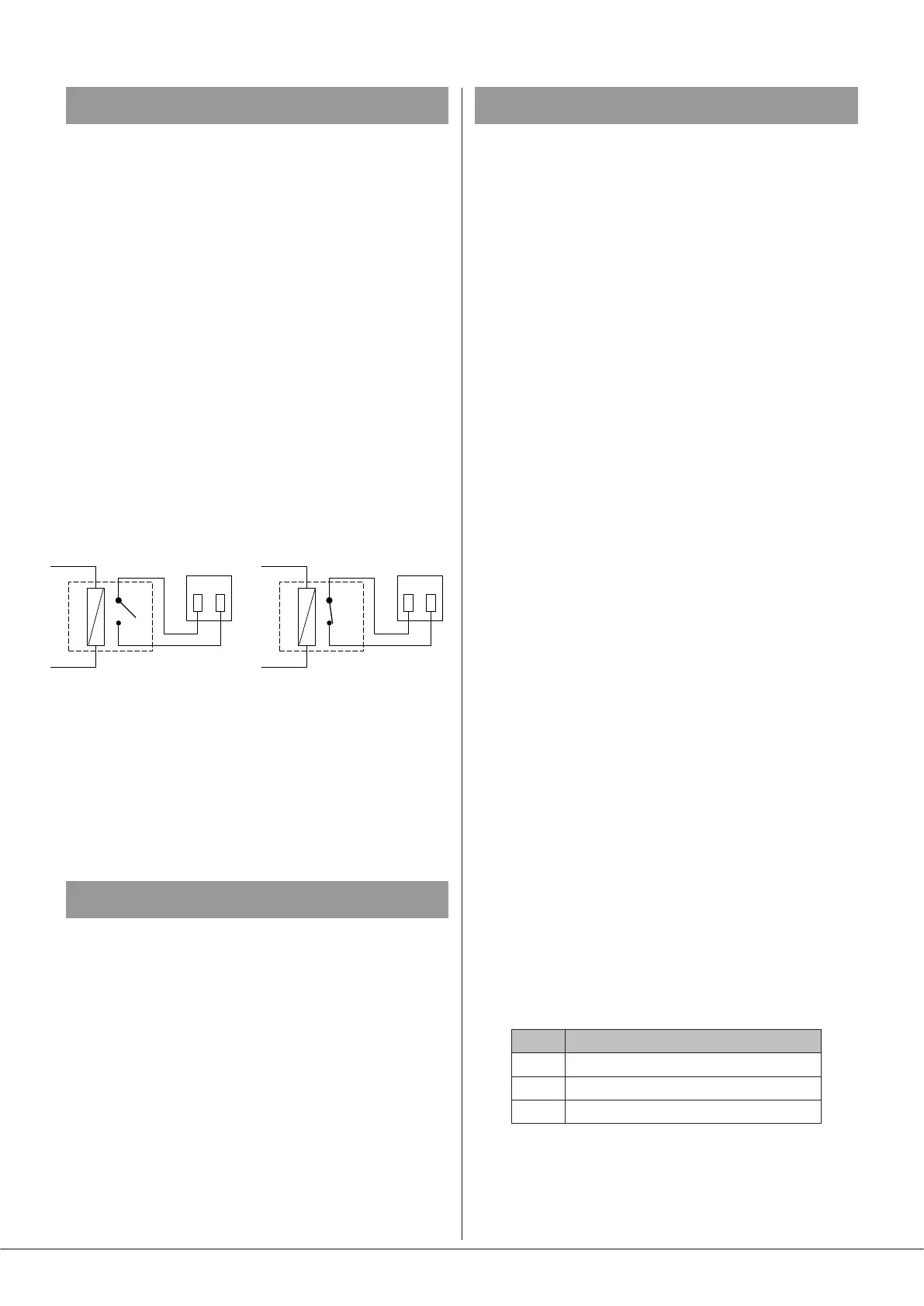
REMOTE MUSIC MUTE TERMINATIONS
1 2
MUSIC MUTE
INPUT
RELAY
NORMALLY OPEN (N/O)
CONNECTION
1 2
MUSIC MUTE
INPUT
RELAY
NORMALLY CLOSED (N/C)
CONNECTION
Note that any signal applied to the Facility Port – either from
a remote active module, or as a hard-wired direct input, will
also be muted by the action of Music Mute.
When Music Mute is active, the front panel red MUSIC MUTE
LED [5] illuminates.
Auto Power Down
A Cloud 24 Series mixer-amplier is extremely energy-
efcient, but can be made even more so by enabling the
Auto Power-Down feature. When active, the signal level
is constantly monitored and if no signals from either zone
output are measured for 15 minutes, the unit enters a “Sleep”
mode, minimising power consumption. If a signal is detected
while in Sleep Mode, the unit “wakes up” in approximately
two seconds: if the signal is due to a line input, the volume
will be faded up over a period of three seconds.
Units are shipped with the Auto Power Down function
disabled. It may be enabled by removing internal jumper J10.
See page 25 for location of PCB jumpers.
Options and Additional Information
Multi-zone Applications
Where the sound system specication calls for separate
control in several zones, multiple 24 Series mixer-ampliers
can be used.
Signal sources can be parallel-connected to several inputs as
required, but care must be taken to ensure the output stage
of the signal source is capable of driving the resulting lower
input impedance.
The impedance of the line inputs (music inputs) is greater
than 10 kohms and it is reasonable to assume that most
op-amp based signal sources are able to drive lower loads,
allowing the line inputs on several ampliers to be paralleled
without any issues. The input impedance of the mic inputs
is 3.3 kohms, making them suitable for microphones with a
nominal impedance of 600 ohms or less. A single 600 ohm
microphone could therefore typically be connected to four
paralleled mic inputs.
If these guideline gures cannot be adhered to, the use of
suitable mic or line distribution ampliers is recommended.
To avoid any problems associated with differences in mains
supply earthing, we recommend that all 24 Series mixer-
ampliers used in a multi-zone application should be co-
located and connected to a common mains supply.
Note that when using multiple 24 Series mixer-ampliers
in a 19” rack, suitable ventilation arrangements must be
made to ensure that lower ampliers do not cause those
above to overheat (see Ventilation at page 13 for further
information)..
Control of music source and level
via external DC
It may be necessary in some installations to adjust the music
level and select music source in one or both zones from an
external AV control system. If the REMOTE port(s) are not
required for RL-1/RSL-6 Series remote control plates, they
may be used to receive DC voltages from the external system
to effect these adjustments.
Both music source selection and level can be controlled over
their full ranges with a DC voltage of 0 to +3.3 V. The pinout
of the REMOTE port is as follows:
PIN USE
1 0 V ref.
2 Music level control (0 to +3.3 V)
3 Music source selection (0 to +3.3 V)