24 Series Installation and User Guide V1.0
25
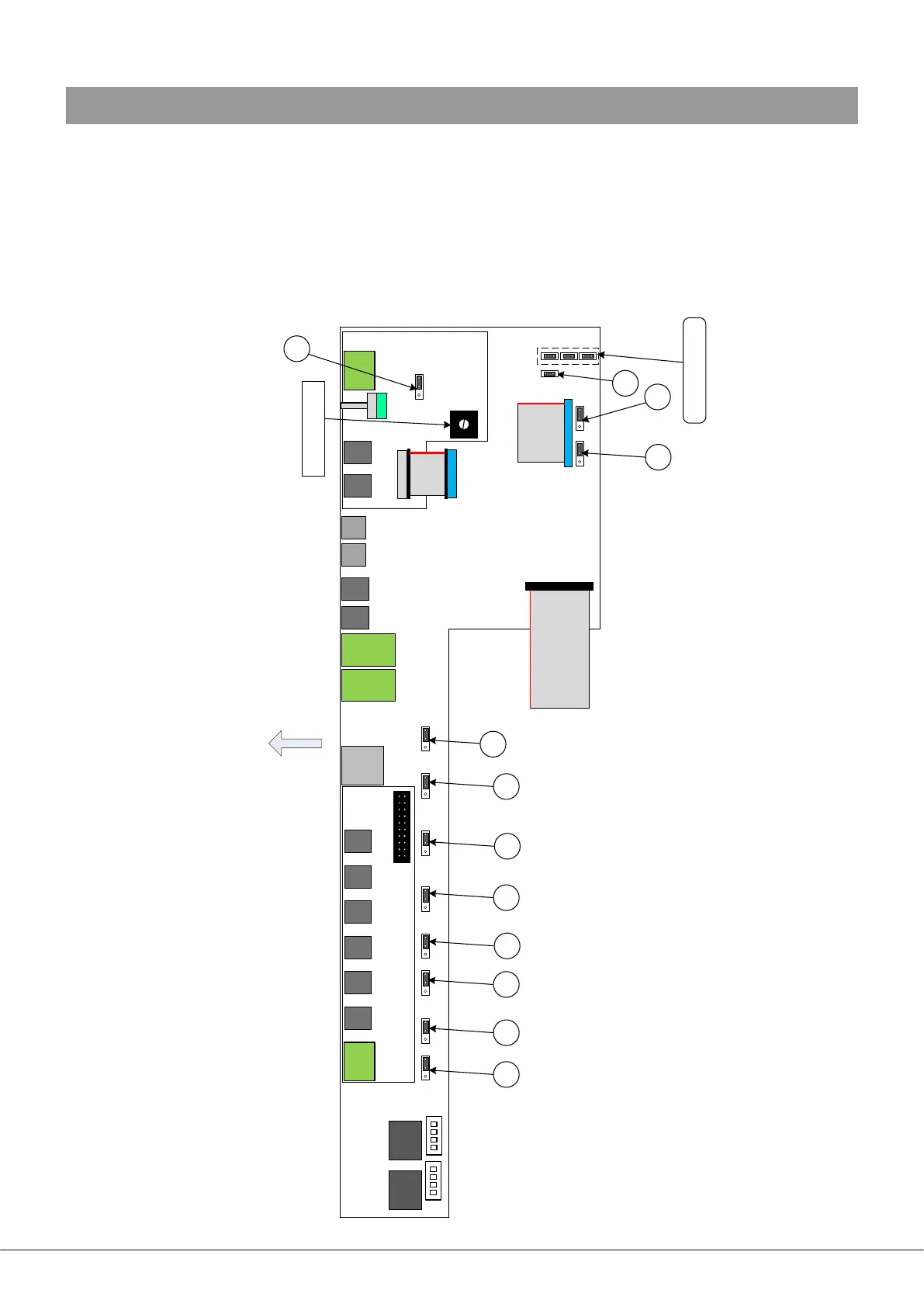
APPENDIX
PCB jumper locations
24 Series mixer-ampliers have various internal jumpers, the setting of which may require alteration during installation. The
diagram below shows the locations of the internal jumpers (not to scale), all of which are located on the main PCB. The table
below lists each jumper and its purpose, together with the factory default setting.
All “user” jumpers have two possible positions; the black rectangle in the symbol on the diagram below indicates the default
setting. If any jumpers need to be changed, turn the unit off and disconnect it from the mains. Undo the seven screws securing
the top cover of the unit (NB one is top centre of front panel) and remove it. Use a pair of small pliers to gently remove the
jumpers from the PCB headers and reposition them as required. Ret the top cover using the same screws.
J11
J12
J10
J2
J3
J4
J5
J6 J7 J8
MAIN PCB
UPPER PCB
(MIC INPUT)
UPPER PCB
(MUSIC EQ/UTILITY)
TO POWER/PSU
MODULE
CHIME LEVEL TRIM
REAR OF UNIT
TO REAR PANEL PCB
J1
NOT TO SCALE
POWER MODULES &
FRONT PANEL PCB
NOT SHOWN
J9
J13/14/15:
FACTORY USE ONLY!