24 Series Installation and User Guide V1.0
26
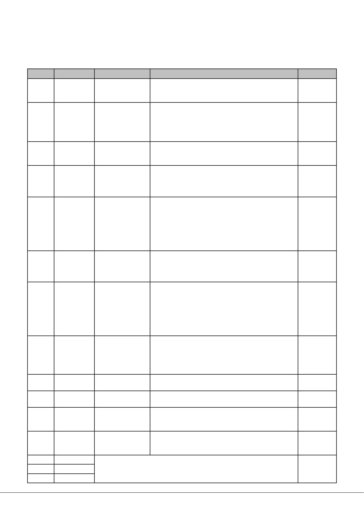
Table of internal jumpers and default settings
The table below lists each jumper and its purpose, together with location and factory default setting.
JUMPER LOCATION DESCRIPTION EFFECT DEFAULT
J1 Main PCB
Utility output music
source
Z1: Music source for utility output is current Zone 1
selection.
L1: Music source for utility output is always Line Input 1
Z1
J2 Main PCB
Music mute N/O or
N/C
N/O: connect the pins of the MUSIC MUTE connector
together to mute Line Inputs 1 to 4 and the Facility Port.
N/C: remove a short-circuit across the pins of the MUSIC
MUTE connector to mute Line Inputs 1 to 4 and the
Facility Port.
N/O
J3 Main PCB
Facility Port audio
routing
Z1: Audio input at Facility Port is routed to Zone 1 only.
ALL: Audio input at Facility Port is routed to Zone 1 and
Zone 2.
Z1
J4 Main PCB
Mic-over-Facility
Port priority
DIS: The mic signal will be mixed at full level with the
Facility Port input.
EN: A signal at the mic input will cause a signal from the
Facility Port to duck.
DIS
J5 Main PCB
Force Zone 1 front
panel music source
selection
SW: when Z1 LOCAL/REMOTE switch is set to REMOTE,
front panel ZONE 1 MUSIC SOURCE switch is disabled
and music source selection is made from remote control
plate/module.
FR: when Z1 REMOTE/LOCAL switch is set to REMOTE,
front panel ZONE 1 MUSIC SOURCE control remains
operative.
SW
J6 Main PCB
Zone 1 remote port
type
RSL4: Remote music source/level control plate in Zone 1
is an RSL-4.
RSL6: Remote music source/level control plate in Zone 1
is an RSL-6.
RSL-4
J7 Main PCB
Force Zone 2 front
panel music source
selection
SW: when Z2 LOCAL/REMOTE switch is set to REMOTE,
front panel ZONE 2 MUSIC SOURCE switch is disabled
and music source selection is made from remote control
plate/module.
FR: when Z2 REMOTE/LOCAL switch is set to REMOTE,
front panel ZONE 2 MUSIC SOURCE control remains
operative.
SW
J8 Main PCB
Zone 2 remote port
type
RSL4: Remote music source/level control plate in Zone 2
is an RSL-4.
RSL6: Remote music source/level control plate in Zone 2
is an RSL-6.
RSL-4
J9
Mic input
sub-board
Mic Input phantom
power
OFF: Mic Input phantom power off.
ON: 12 V phantom power available at Mic Input.
OFF
J10 Main PCB APD enable
PRESENT: APD (Automatic Power Down) inactive.
ABSENT: APD enabled
PRESENT
J11 Main PCB
Zone 1 Line 4
Priority
DIS: Line Input 4 operates as other line inputs in Zone 1.
EN: a signal at Line Input 4 will take priority in Zone 1
over all other Line Inputs, but not over the Facility Port.
DIS
J12 Main PCB
Zone 2 Line 4
Priority
DIS: Line Input 4 operates as other line inputs in Zone 2.
EN: a signal at Line Input 4 will take priority in Zone 2
over all other Line Inputs, but not over the Facility Port.
DIS
J13 Main PCB
FOR FACTORY USE ONLY – DO NOT FIT A JUMPER HERE ABSENTJ14 Main PCB
J15 Main PCB