PM4/8/12/16 & PM4/8-SA Installation and User Guide v1.1
26
Powering SA models from a Cloud DCM-1
SA models of the PM may be powered from a Cloud DCM-1 Digitally Controlled
Mixer. Other Cloud host mixers, such as the Z4II/Z8II or 46/50, have insufcient spare
current capacity to power SA models of the PM.
Note that if the PM is being powered from a DCM-1, an external PSU should not be
simultaneously connected.
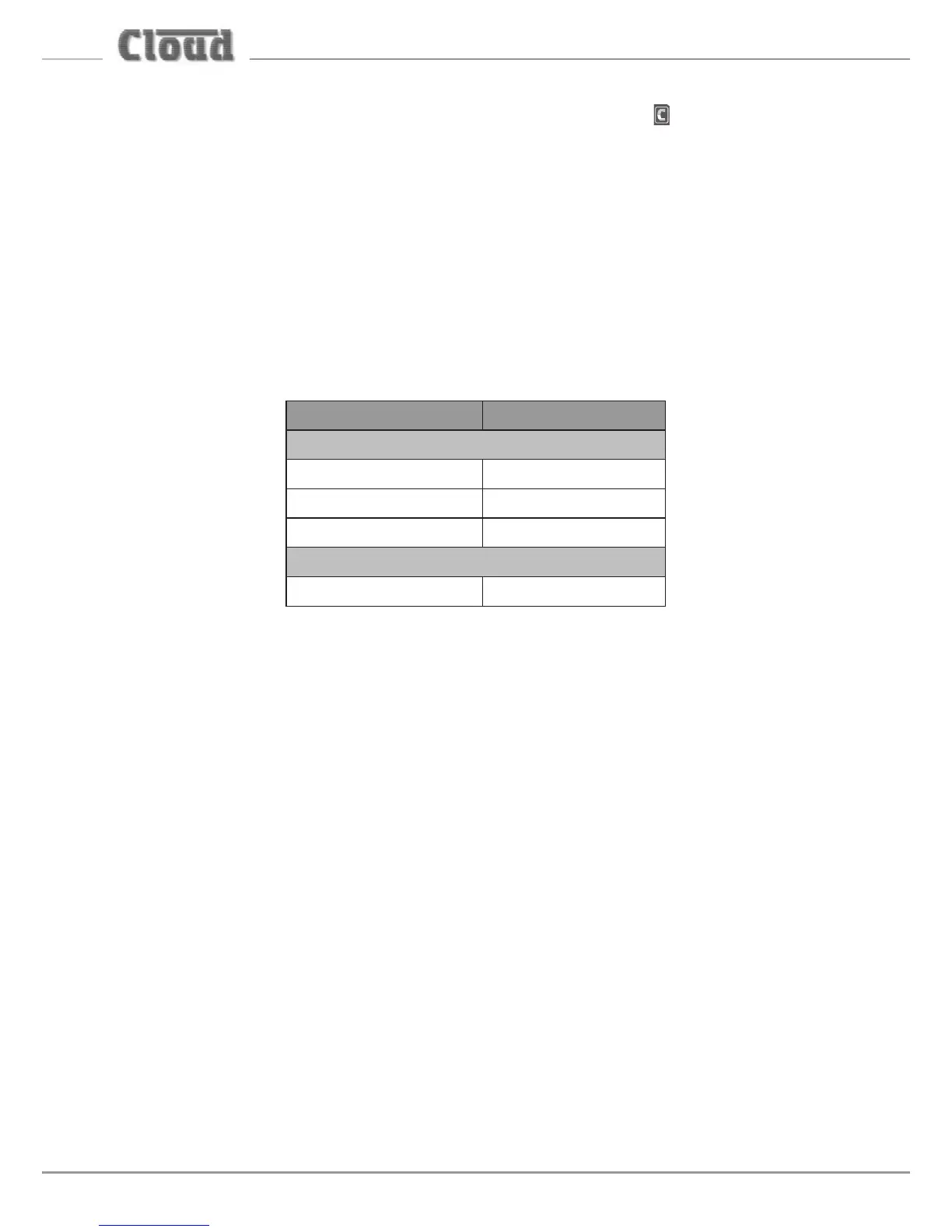
The DCM-1 has 650 mA of spare current capacity for powering external items,
but this gure will be reduced if any remote control or remote input plates are
connected to the DCM-1. De-rate the DCM-1’s current capability according to the
following table (gures are per plate):
Option* Required Current
Active Remote Plates
BE-1 24 mA
LE-1 22 mA
ME-1 43 mA
Remote Control Plate
CDR-1(F) 50 mA
*Fitting loudspeaker EQ modules to the DCM-1 does not de-rate its external current capability.
There are two ways in which a PM-SA can be supplied with DC power by a Cloud
DCM-1:
1. Via the Digital Paging Interface. The CAN PORT OUT connector on the PM-SA is
wired for power, so a PM connected via this can obtain power through the interface.
In systems with multiple, “daisy-chained” PM-SAs (or PMs), it is only the ‘last’ PM/
PM-SA on the network - i.e., that connected directly to the DCM-1 - which can
be powered in this way. See “Systems with multiple paging microphones” on page
44 for more information. Note that when using the Digital Paging Interface, the
maximum recommended cable length between the DCM-1 and the ‘last’ PM should
not exceed 50 m. If longer cable lengths are required, then an external PSU should be
connected to the PM.
2. Via the analogue interface. The PM-SA’s analogue interface allows for DC power.
The ‘+V’ and ‘0V’ terminals of the internal connector TERM1 should be wired to the
‘+V’ and ‘0V’ pins respectively of the access connector of the DCM-1. This method
of powering requires an additional core in the access cable (the ‘0V’ connection
will need to be made in any case for the zone selection to function). Only one
microphone may be powered from the DCM-1 in this way.