PM4/8/12/16 & PM4/8-SA Installation and User Guide v1.1
49
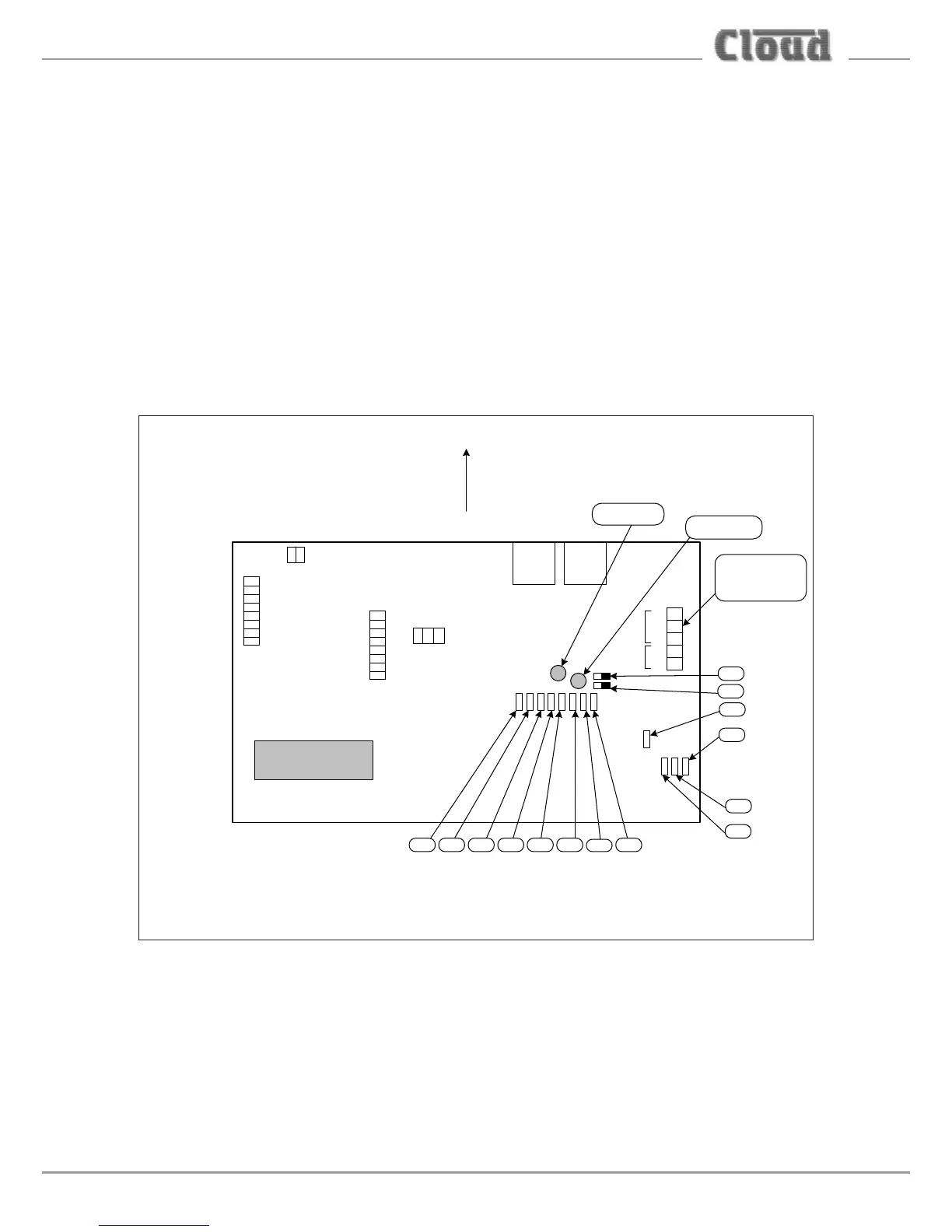
APPENDIX
PCB layout diagrams
When removing jumpers we recommend that the link is left connected to one leg of
the header to prevent loss of the link.
When making internal adjustments please ensure that you:
• Disconnect power to the unit before accessing the PCB. If the microphone is
powered from another unit, this will mean removing the appropriate connection.
• Only reassemble the unit using the original screws.