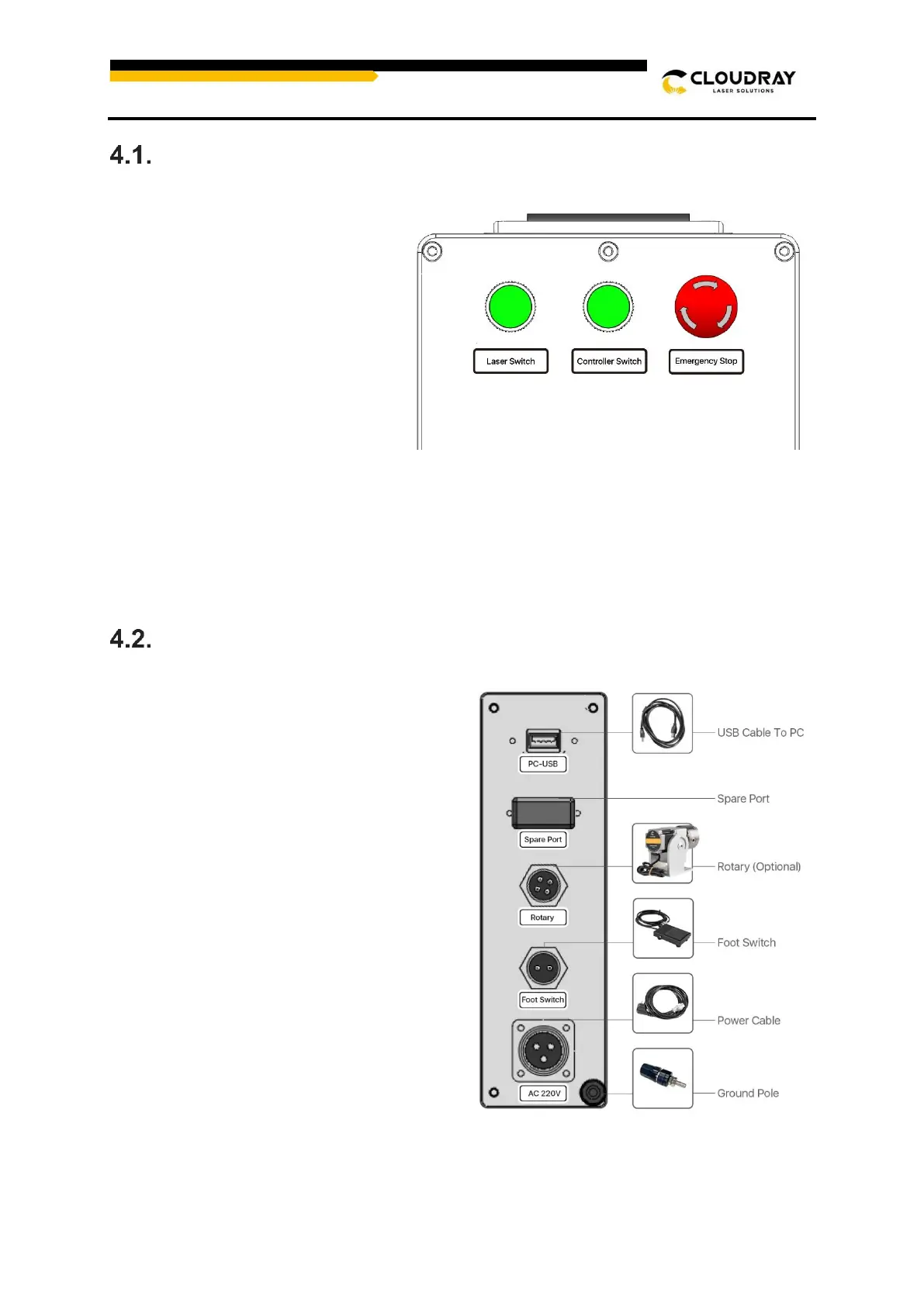
Control Elements on the Front
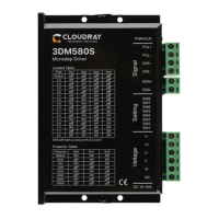
Laser Module Interface (Reverse Side)
PC-USB——This port connects the device
to your control computer.
Spare Port——Alternate port, used if
necessary.
Rotary(Optional)——This port enables
use of a rotary axis engraver with a 4-pin
connection cable. (Compatible rotary axis
devices are sold separately.)
Foot Switch——This port enables optional
pedal control of laser activation to free your
hands for manual adjustment of the target
material.
Power Input——This 3-pin port connects to
the device's standard 3-prong power cord
(Voltage and power cord types are
standard according to actual conditions)
Laser Switch——Activates the fiber
laser power. Press this last during
startup and first during shutdown.
Controller Switch——Activates the
controller and galvo power. Press
this second during startup and
shutdown.
Emergency Switch——Activates
the machine main power. Rotate this
first during startup and press during
shutdown. In case of emergency,
press to cut off the power at any
time.