MAN.219 Rev.8 ENG - Use and maintenance manual S19N page 27 of 71
It will be care and responsibility of the operators, at the end of
the operations, to reset the original conditions, including the
resealing with seal compulsorily branded “C.M.C.”.
4.6.3 Emergency operations in case of endothermic
engine failure
In case of emergency (engine anomaly, fuel exhaustion, and/or breakage
of a hydraulic part, etc.) to get the pressure inside the hydraulic circuit
necessary for the functioning of the platform components, it is possible to
use the electropump (par. 4.5), if present, or the 110/120/230 V electrical
engine (par. 3.1.1) if supplied as *optional.
To withdraw the aerial part, using the aforementioned feeds, operate the
MEWP through the emergency control station on the turret (Picture 10).
4.6.4 Emergency operations in case of electrical sys-
tem failure
In case of electrical emergency to get the pressure inside the hydraulic cir-
cuit necessary for the functioning of the platform components, it is possible
to use the endothermic engine or the manual pump.
To withdraw the aerial part, using the aforementioned feeds, operate the
MEWP through the emergency control station on the turret (Picture 10).
4.6.5 Simultaneous failure of hydraulic and electrical
system
In case of emergency (simultaneous failure of the hydraulic and electrical
system), to obtain the pressure inside the hydraulic circuit, you should use
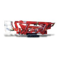
the manual pump. Bring the manual pump handle supplied on the chassis
and insert it in the proper point of pumping (Picture 17), near the emergen-
cy control station.
First carry out the recovery operations of the aerial part, to get
the basket operator safe.
Picture 17: manual pumping lever to insert.
Recovery procedure for aerial part:
1. Stall the engine by the key SK (Picture 4), reach the main distribu-
tor shown in Picture 18 and remove the carter;