MAN.243 Rev.5 ENG - Use and maintenance manual S28 page 16 of 138
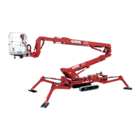
2.3.1 Frame
The frame 1 (Picture 3) is a structure in quality steel, able
to equally divide the equipment’s weight when the
MEWP is in transport position. The frame has 4 oil-
pressure jack beams for stabilization [2 front stabilizer
cylinders 2 (Picture 3), 2 rear stabilizer cylinders 3
(Picture 3)]. The basis for the bearing 4 is placed on the
frame (Picture 3). It enables the swinging of the
equipment through the turn-table.
2.3.2 Turret
The turret 5 (Picture 3), in quality steel, is secured to the
bushing (bearing). A hydraulic engine, with brake
normally closed, constrained to the turret, allows the
rotation of the superstructure.
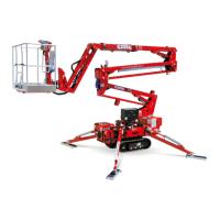
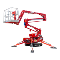
2.3.3 First telescopic boom group
The first telescopic boom group 6 (Picture 3) is
composed by three elements: a fixed boom and two
extendable booms.
The extension (or withdrawal) of the telescopic boom is
given by operating the “telescopic boom extension
cylinder”.
The movement of the boom (lifting and lowering) is given
by the lifting hydraulic cylinder. Such cylinder is secured
to the turret (cylinder side) and to the fixed boom (piston
side) and is supplied with safety valves.
2.3.4 Second telescopic boom group
The second telescopic boom group 8 (Picture 3) is
hinged to the first telescopic boom by a rod 7 (Picture 3).
The telescopic boom is composed by three elements:
one fixed boom hinged to the rod and two extendable
booms.
The extension (or withdrawal) of the telescopic boom is
given by operating the “telescopic boom extension
cylinder”.
The lifting (or lowering) of the telescopic boom is given
by operating the “lifting cylinder of second telescopic
boom group”.