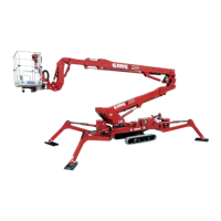
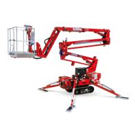
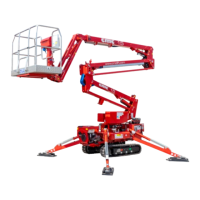
MAN.243 Rev.5 ENG - Use and maintenance manual S28 page 94 of 138
6 Electrical system
The electrical system is attached to this manual.
Any operation, requiring interventions on the
components of the machine, shall carried out
by authorized and trained staff.
It is forbidden to replace the components for non-
authorized staff. Many components of the
MEWP have been calibrated: a correct
calibration of these parts (which is possible
only in C.M.C. or in authorized Services) is
important to assure the safety of the machine.
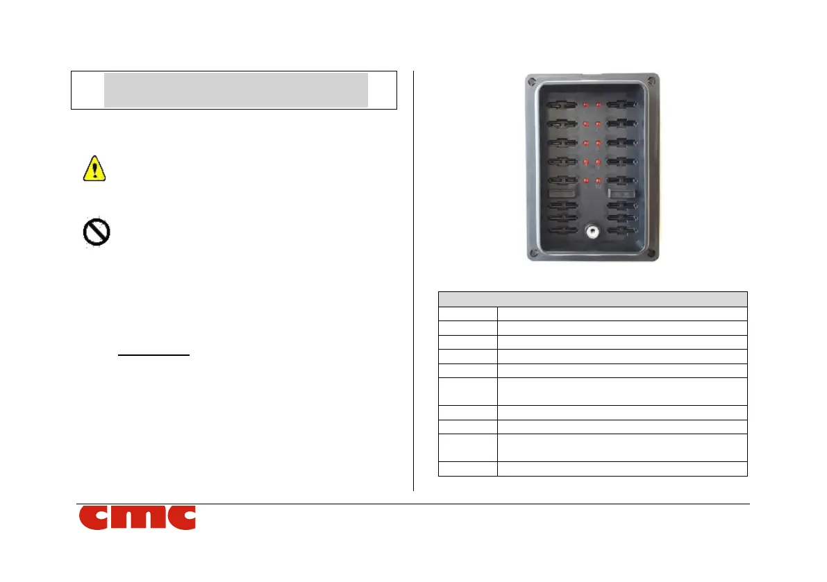
• FUSE BOX (Picture 119):
At view on machine switching on/off station, there
is a fuse box where it is possible to identify all the
machine fuses. You can also locate the burnt
ones through the lighting of a related spy.
Picture 112: fuse box.