CNC 6040 Router / Engraver System
CNCDIY CNC Routing Machines System User’s Manual
22
Step 3 Assuming the poles for step 2
After find out the group of wires, you can assume that one group is A coil and the other group is
B coil!
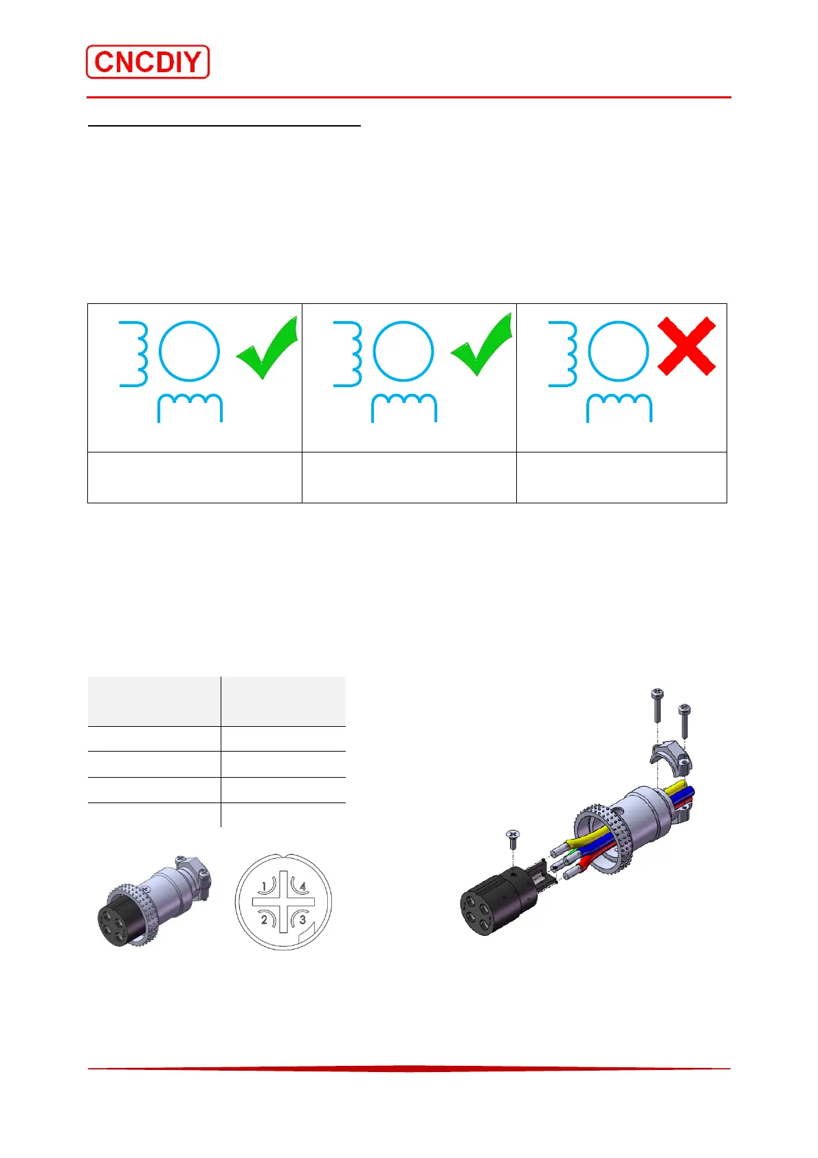
The A+ pole and the A- pole can be exchanged. The B+ pole and the B- pole can also be
exchanged! But, the any wire of A coil cannot be exchanged with any wire of B coil, it will
burn the control system!
c) correct connection c) exchange the coil ends at
the same coil (phase)
c) exchange the coil ends
with different coils (phases)
3-9-2-2 Header of cable (Connect with the control box)
You must following the “Methodology of finding the poles of stepping motor” for this part!
Because the Pin number of the 4 pins head is represented the poles connection of the CNC
controller, if the connection of poles was wrong, the controller would be burnt!
Pin Number Stepping Motor
poles
1 A+
2 A-
3 B+
4 B-
Outlook Welding Pins Exploded view
M
A+
A‐
B+ B‐
M
A+
B‐
B+ A–
M
A‐
A+
B‐ B+



 To Next Page