Electrical installation and wiring
4-12 Chapter 4: Installation 98-145168-A
Wiring diagram
See Wiring – overview on page 4-7.
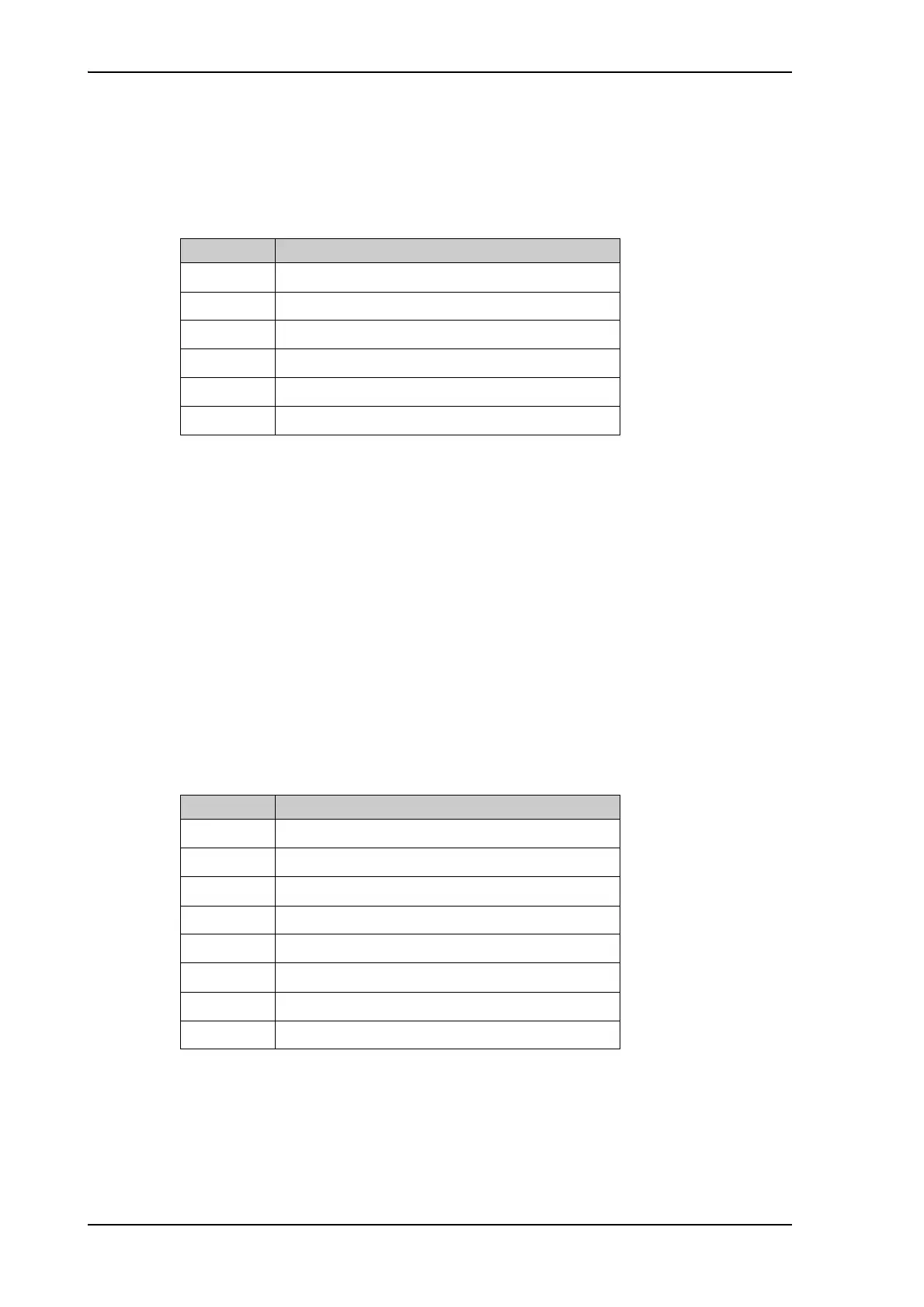
Pins for CMU 1 and 2
Description
The Communications Management Unit (CMU) or equivalent is responsible for integrating
data communications or datalinks on the aircraft. The CMU manages communication
across multiple subnetworks, including VHF and SATCOM networks.
4.3.8 To wire cockpit audio 1 and 2
ARINC-781 compliant.
See also the wiring of the cockpit audio discrete interfaces in section 4.3.10.
Wiring diagram
See Wiring – overview on page 4-7
Pins for cockpit audio 1 and 2
Description of the cockpit audio 1 and 2
There are two 4-wire interfaces to be connected to a headset.
CSDU pin Description
MP07J Data to CMU 1 and 2. A. (A429 output)
MP07K Data to CMU 1 and 2. B. (A429 output)
MP03A Data from CMU 1. A. (A429 input)
MP03B Data from CMU 1. B. (A429 input)
MP03J Data from CMU 2. A. (A429 input)
MP03K Data from CMU 2. B. (A429 input)
CSDU pin Description
MP04A Cockpit audio input 1. High.
MP04B Cockpit audio input 1. Low.
MP05A Cockpit audio output 1. High.
MP05B Cockpit audio output 1. Low.
MP04J Cockpit audio input 2. High.
MP04K Cockpit audio input 2. Low.
MP05J Cockpit audio output 2. High.
MP05K Cockpit audio output 2. Low.