Electrical installation and wiring
4-20 Chapter 4: Installation 98-145168-A
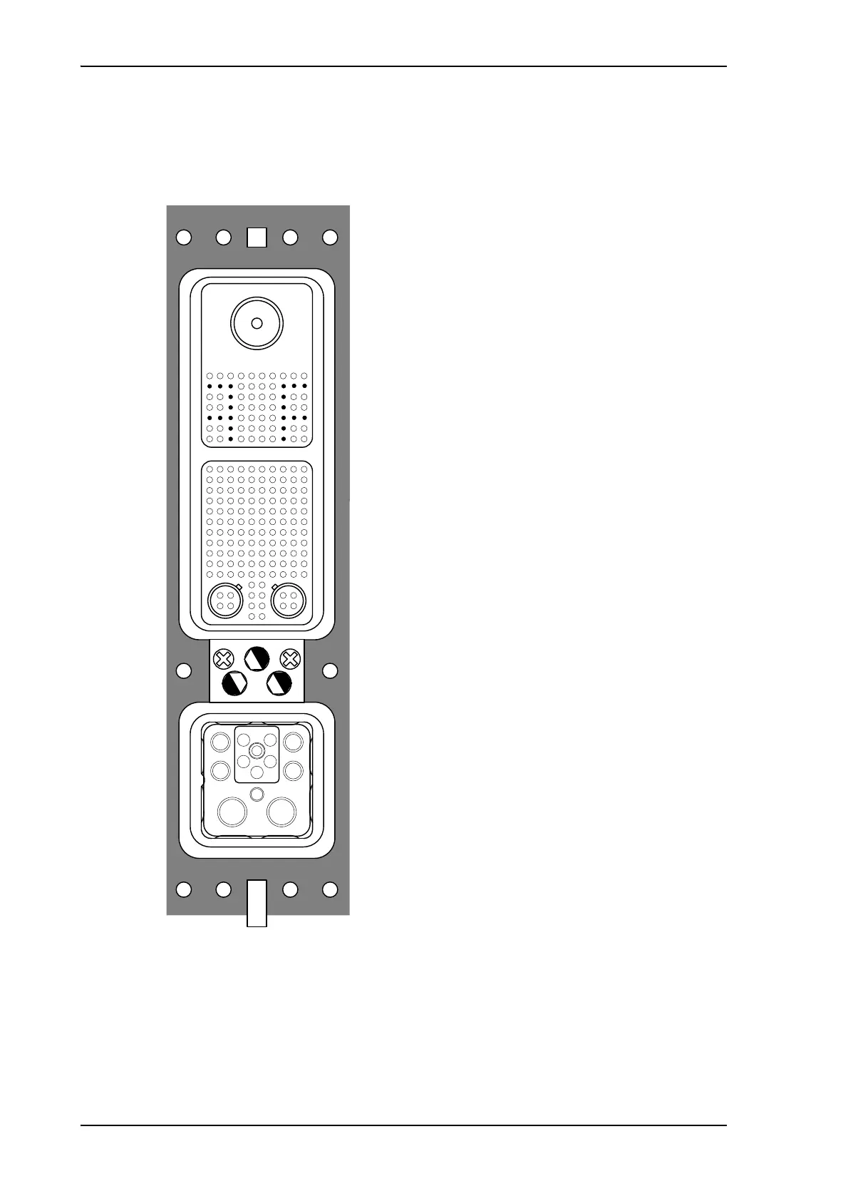
4.3.19 CSDU ARINC 600 connector block
ARINC 600 connector drawing - overview
Figure 4-8: CSDU ARINC 600 connector specifications
ABCDEFGHJK
ABCDEFGHJK
7
6
5
4
3
2
1
7
6
5
4
3
2
1
9
8
10
14
13
12
15
3
2
4
1
4
3
1
2
11
1T 2T
76
5
98
1110
12
2
4
1
3
Pin 71
Top Plug (TP):
Insert arrangement 08
Receptacles
1 Size 1 Coax cavity
50 Size 22 sockets
• = empty cavity
Middle Plug (MP):
Insert arrangement 120Q2
Receptacles
2 Size 8 Quadrax cavities
118 Size 22 sockets
Bottom Plug (BP):
Insert arrangement 12F5C2
Receptacles
4 Size 12 pins
1 Size 16 pin,
2 Size 5 coax cavities
5 Size 16 optical cavities (not used)
Index pin code 81 (5,2,2)
Light areas are key holes in receptacle.
Size 2 Shell receptacle