Electrical installation and wiring
4-18 Chapter 4: Installation 98-145168-A
The following list shows the pins used for the Micro USB interface (Front connector on the
CSDU).
Description of the maintenance interfaces on the CSDU
Use the maintenance interface on the front of the CSDU or the AISD 1/EFB 1 (Ethernet 11)
interface for maintenance purposes. These interfaces are only accessible for maintenance
when the aircraft is on the ground. The interfaces can be accessed from a PC with Ethernet
interface or a Micro USB connector.
The maintenance interface has the following characteristics:
• Ethernet 11 (AISD 1 / EFB 1):100 Base-T /10 Base-T Ethernet / IEEE 802.3
• Front Panel Micro USB (115200 bps)
Person Activated Self Test (PAST) Push-To-Test button
The CSDU resets the system and initiates a Person Activated Self-Test "PAST" when the
Push-To-Test button on the front panel is pressed for at least 2 seconds and less than 20
seconds and while in Maintenance Allowed mode (i.e. a PC is connected via the Micro USB
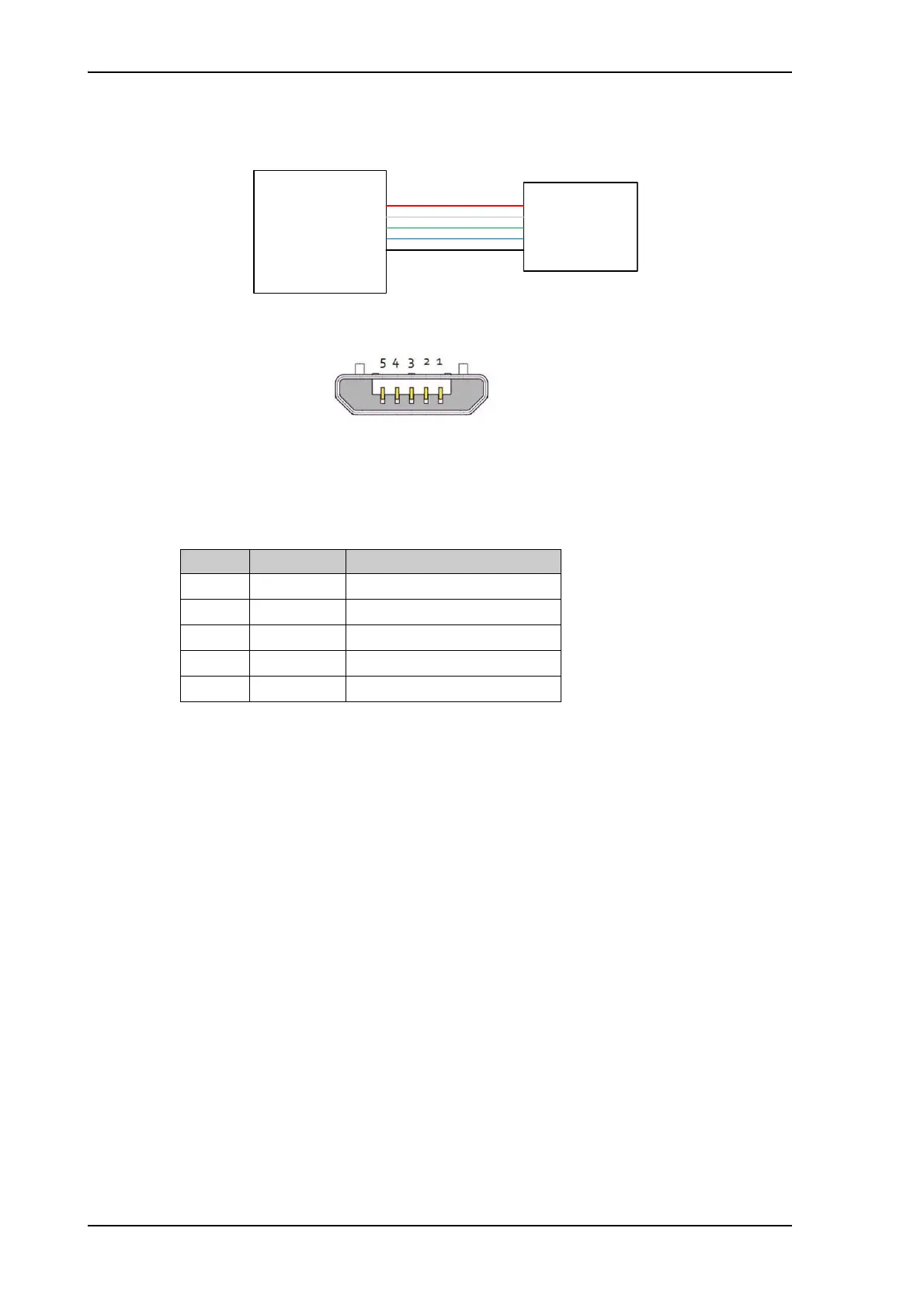
Figure 4-5: Wiring Maintenance PC via Micro USB
CSDU
1
2
3
4
5
Maintenance
PC
Micro USB
1
2
3
4
5
VCC
D-
D+
ID – Not used
GND
Figure 4-6: Micro USB maintenance connector of the CSDU, face view of
engaging end
Pin Pin Name Description
1VCC+5 VDC
2D-Data -
3D+Data +
4IDNot Used
5 GND Signal ground