Connector panel of the BDU
98-175666-C Chapter 3: Interfaces 3-2
3.1.3 Rx/Tx connectors for modem
Connect the Rx and Tx channels of the modem to the Rx and Tx connectors of the BDU
with the 2 supplied Rx/Tx cables (75 Ohm coax, F-F, 1 m).
For step-by-step guidelines how to set up the VSAT modem see Miscellaneous on
page C-1.
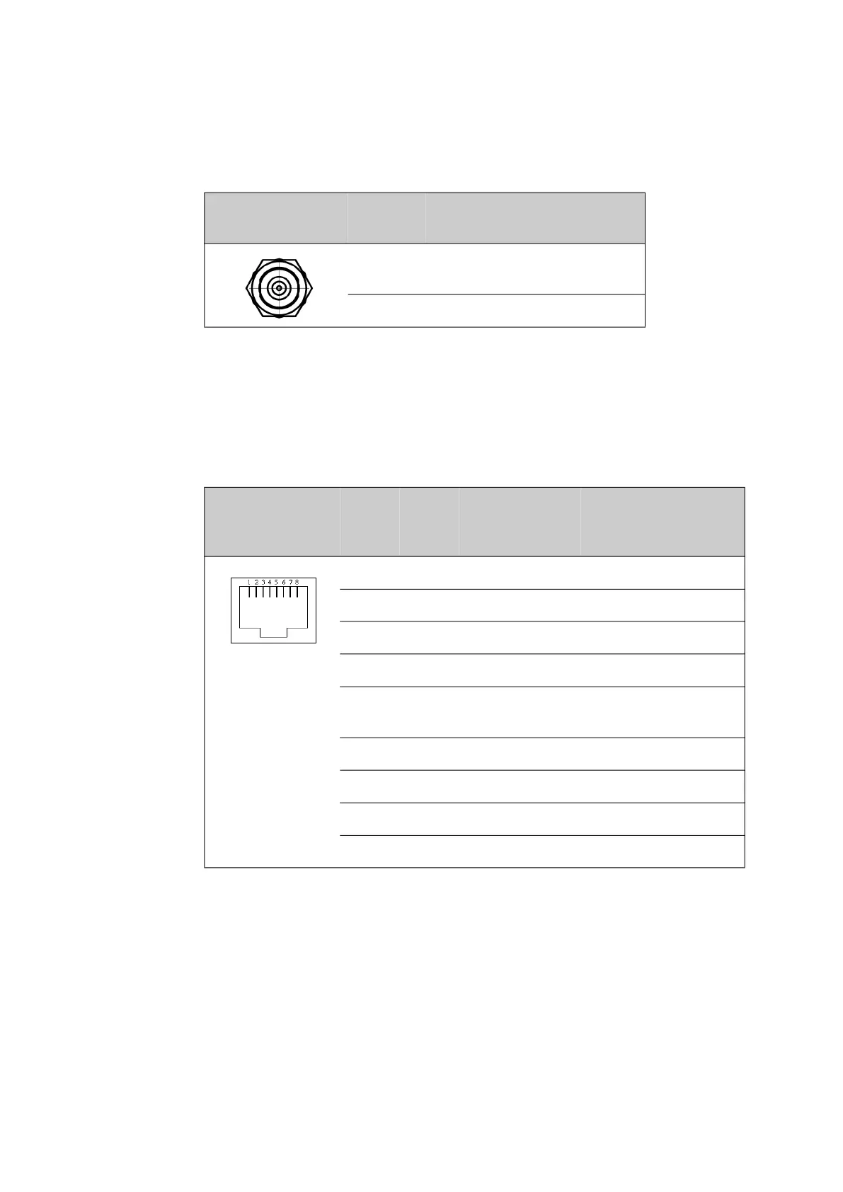
3.1.4 NMEA 0183 RJ-45 connector
Connect the shipʼs gyro to the RJ-45 connector marked NMEA.
Outline
(on the BDU)
Pin
number
Pin function
1 Inner conductor:
10 MHz clock, VSAT Rx/Tx
2 Outer conductor: GND (Shield)
Table 3-3: F connector, Rx and Tx, outline and pin assignment
Outline
(on the BDU)
NMEA
Pin I/O Signal Pin function
1 O RS-422 Line B (+) Future use
2 O RS-422 Line A (-) Future use
3 I RS-422 Line B (+) Heading, balanced
4 O RS-232 TxD Future use
5 RS-422 shield Connect only at one
end
6 I RS-422 Line A (-) Heading balanced
7 RS-232 GND Heading, single
8 I RS-232 RxD Heading, single
Shield PCB ground PCB ground
Table 3-4: NMEA 0183 RJ-45 connector, outline and pin assignment
 Loading...