To connect the ADU, BDU and modem
98-175666-C Chapter 2: Installation 2-26
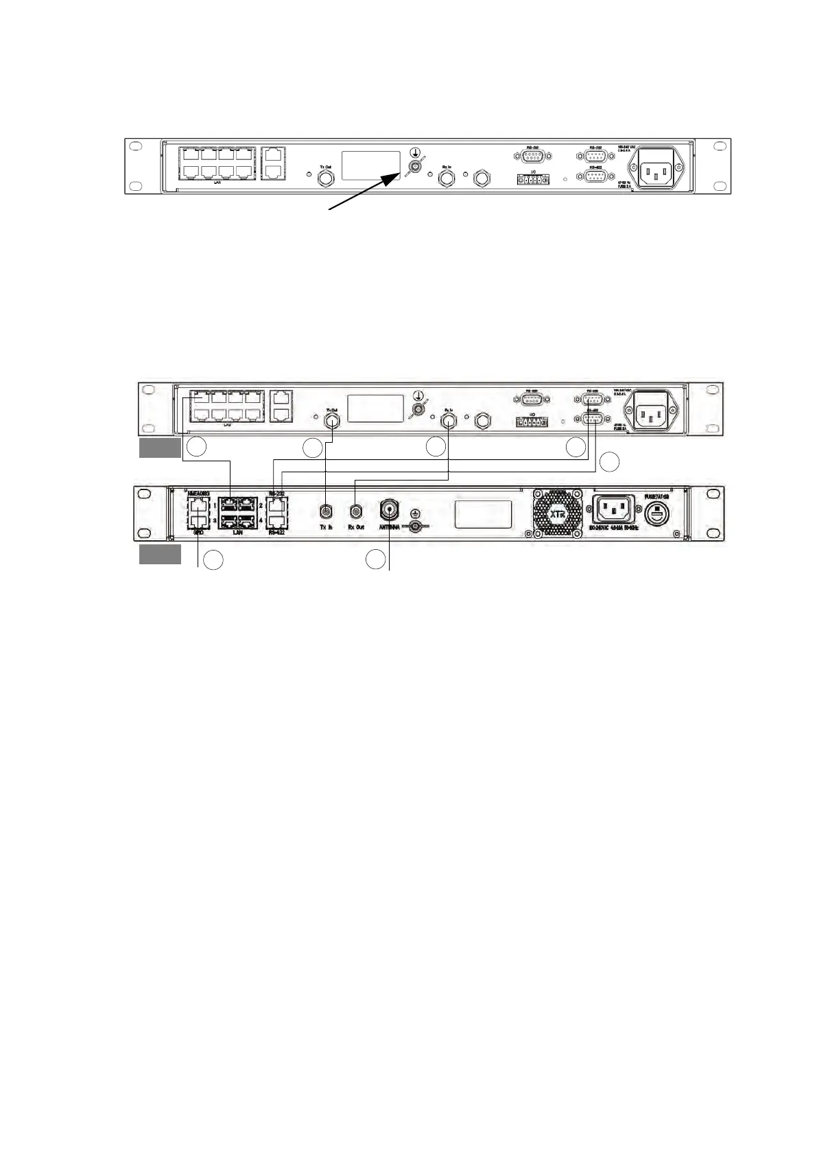
2.7 To connect the ADU, BDU and modem
The following sections show how to connect the ADU, BDU and the modem.
1. Connect the antenna cable to Antenna at the BDU and the antenna.
2. Connect Rx Out at the BDU to Rx In at the modem with the supplied cable (75 Ohm
coax, F-F, 1 m).
3. Connect Tx In at the BDU to Tx Out at the modem with the supplied cable (75 Ohm
coax, F-F, 1 m).
4. Connect RS-232 on the BDU to RS-232 at the modem.
5. Connect RS-422 on the BDU to RS-422 at the modem.
6. Connect LAN1 at the BDU to the upper left RJ45 connector at the modem.
7. Connect the green terminal block for the heading input from the gyro. For pin
allocation see NMEA 0183 RJ-45 connector on page 3-2.
2.8 Integration of a 3rd party IP device
This section describes how to integrate a 3rd party device inside the antenna radome
of the SAILOR 1000 XTR GX-R2. The antenna has the following interfaces for the
integration:
• Power connector
• Communication
• Mechanical interface
Figure 2-27: Ground stud, GMU
Figure 2-28: Connection between ADU, BDU and modem
1
2
3
4
5
6
AC power
AC power
GMU
BDU
7
 Loading...