Integration of a 3rd party IP device
98-175666-C Chapter 2: Installation 2-27
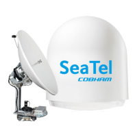
2.8.1 Power connector
The power output options are 12 VDC / 2A and 5 VDC / 2A. The physical interface is a
Molex 105308 4-pin nano-fit connector on the XTR Antenna Control Module (ACM).
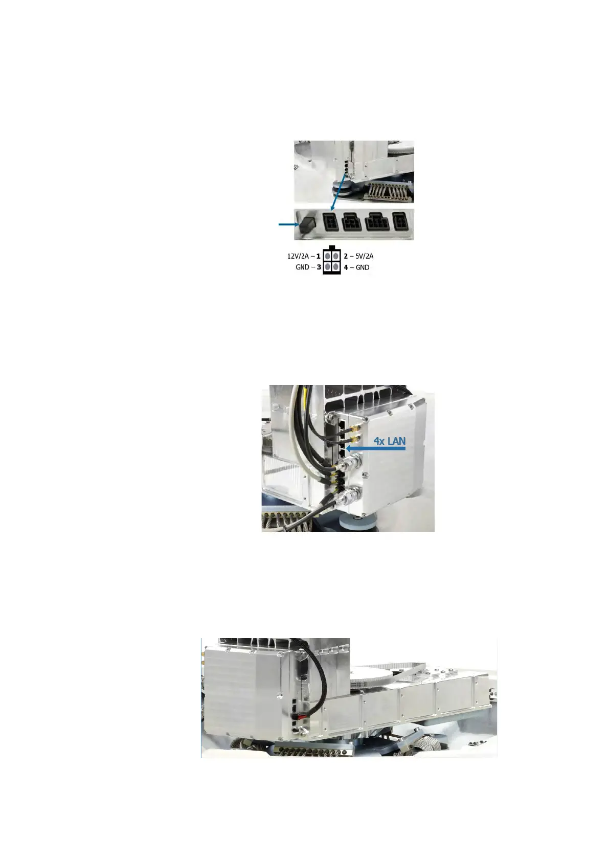
2.8.2 Communication
The ACM has four Ethernet LAN ports. LAN port 1 and 2 can be tunneled to the LAN
ports of the BDU. The BDU LAN port and ACM LAN port are a transparent data channel
that connects two devices.The ACM LAN ports are set up in the web interface
2.8.3 Mechanical interface
The antenna pedestal is prepared for mounting devices on the side of the pedestal.
The mounting screw holes (M5x8mm) can support a special designed mounting
bracket to support mounting of a 3rd party hardware device in the antenna.
Figure 2-29: ADU power on off (left) and ACM 4-pin nano-fit connector
Figure 2-30: ACM LAN ports
Figure 2-31: Mounting pattern on the pedestal
 Loading...