Connector panel of the BDU
98-175666-C Chapter 3: Interfaces 3-4
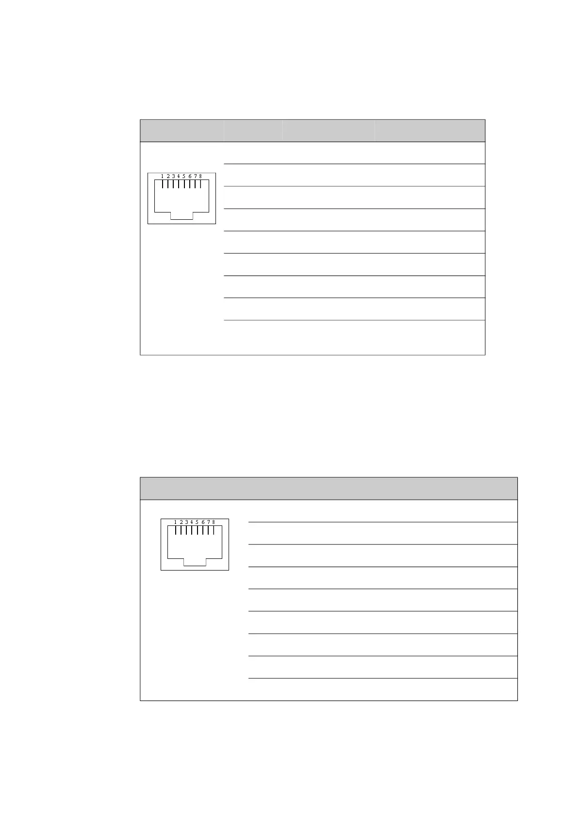
3.1.5 GPIO RJ-45 connector
The Tx mute function can be controlled with a simple switch connected between pin 1
(Tx mute) and pin 2 (12 VDC). The Rx lock function is high and becomes low when the
modem is not in Rx lock.
3.1.6 RS-232 RJ-45 connector
Use the following connector to connect the BDU to the VSAT modem
Outline on BDU Pin I/O Signal Pin function
1 I GPIO1 Tx mute (active high)
2 O 12 VDC / 500 mA Power output
3 O GPIO2 Rx lock (open drain)
4 N/A GPIO3 Future use
5 GND Ground
6 O 12 VDC / 500 mA Power output
7 N/A GPIO4 Future use
8 GND Ground
Shiel
d
PCB ground PCB ground
Table 3-5: RJ-45 GPIO connector, outline and pin assignment
Outline Pin I/O Signal Function
1 I RSSI 2 CM temp out of range
2 I DTR/Rx Lock CM power good
3 I RXD BUC TXD
4 - GND Ground
5 - GND -
6 O TXD BUC RXD
7 I DSR/TX Mute GMU reset
8 I RSSI 1 CM RSSI
Shield - PCB ground PCB ground
Table 3-6: RJ-45 RS-232 connector, male, outline and pin assignment
 Loading...