Settings
98-175666-C Chapter 4: Setup of the antenna 4-15
User defined VLAN's (SNMP from the iDirect Core module / GMU)
12 User defined VLANs are supported. The IDs of the user defined VLANs must be
outside the 1-8 range used internal by the SAILOR BDU/ACU switch. (System VLANs,
see previous section).
User defined VLANS are used to transfer user related traffic to the modem (GMU), via
the BDU. A User defined VLAN set up the BDU LAN Port 2 and 4 as either a T or a U
(trunk or access port), and will automatically set up the BDU LAN 1 as a T
Example: Network setup:
BDU LAN 1 mode: Modem.
BDU LAN 2 mode: Modem controlled.
BDU LAN 3 mode: Modem.
BDU LAN 4 mode: ADU port 2.
BDU LAN 5 mode: Service
ADU LAN 1 mode: service
ADU LAN 2 mode: Lan port 4
User defined VLANs
1010 - 1020 - 1030
System subnet:
VLAN 1: 192.168.1.0/24
VLAN 5: 192.168.0.0/24
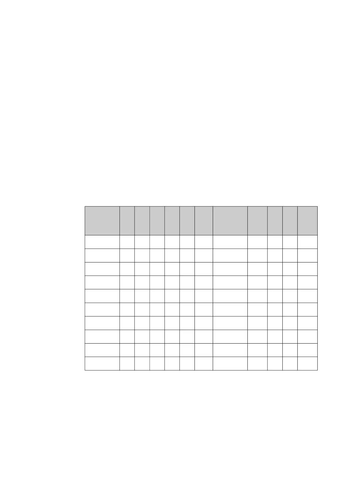
BDU ports
VLAN Id
1 2 3 4 5
BDU
CPU
BDU- ADU
MoCa
ADU
port
s
1 2
ADU
CPU
VLAN 1 U U T U T
VLAN 2
VLAN 3
VLAN 5 U T T
VLAN 6
VLAN 7 U T U
VLAN 8 U T T
VLAN 1010 T T
VALN 1020 T T
VLAN 1030 T T
Table 4-13: VLAN table, example
 Loading...