TN855 CI-DSP-223 Telex (Vega) DSP Tone-Remote Adapter
MT-3/4 Radio Systems
TECHNICAL NOTES
Page 2 of 6
LMRSALES@CODANCOMMS.COM
CODANCOMMS.COMTECHNICAL NOTE:
TN855, REV 12-0-0, © Nov 2018
CANADA/US +1 250 382 8268 | TOLL FREE +1 800 664 4066
Installation:
The A-PNL-AUX96-3 auxiliary connector can be used to connect the Telex DSP-223 to a Codan Base Station with
an AC-3E or CI-BC-4E, as shown in Figure 1. Select the two or four-wire-line operation and setup jumpers J20
and J21on the Telex. For four-wire-line operation, set the jumpers in position ‘B’ and connect the four-wire leased
line outgoing to Pins 4 and 5 and the receive to Pins 3 and 6 of the RJ45 modular connector. For two-wire-line
operation, set the jumpers in position ‘A’ and connect the two-wire leased line to Pins 4 and 5 of the RJ45 modular
connector. Ensure jumpers JU67A (or JU67X for CI-BC-4E) and JU68 are installed on the AC-3E and CI-BC-4E.
On Codan MT-4 modules the CTCSS to Subtone connection is not required (CTCSS is generated internally by the
transmitter).
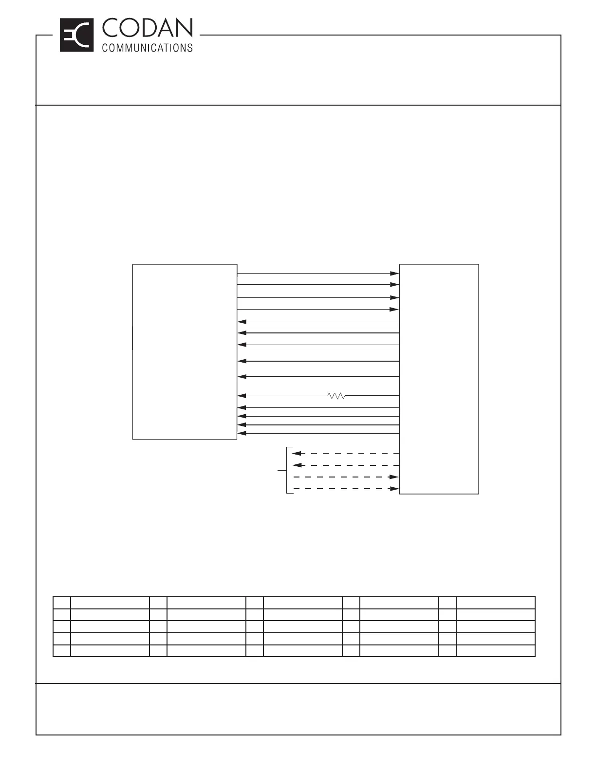
Figure 1: Codan Radio System to Telex DSP-223 connection
DB-25 to A-PNL-AUX96-3 Connector Table (Color coding for Codan cable):
1 YEL/GRN (PTT NC) 6 RED/GRN (F2 NO) 11 VIO/GRN (CTCSS) 16 WHT/GRN (MON COM) 21 BLK/GRN (DIG1)
2 YEL/BRN (PTT COM) 7 RED/BRN (GND) 12 VIO/BRN (RX-) 17 WHT/BRN (F1 NO) 22 BLK/BRN (DIG3)
3 YEL/GRY (MON NO) 8 RED/GRY (DIG0) 13 VIO/GRY (TX-) 18 WHT/GRY (F2 NC) 23 BLK/GRY (DIG5)
4 YEL/ORG (F1 NC) 9 RED/ORG (DIG2) 14 VIO/ORG (PTT NO) 19 WHT/ORG (F2 COM) 24 BLK/ORG (RX+)
5 YEL/BLU (F1 COM) 10 RED/BLU (DIG4) 15 VIO/BLU (MON NC) 20 WHT/BLU (+POWER) 25 BLK/BLU (TX+)
CODAN RADIO EQUIPMENT
P1 (A-PNL-AUX96-3 CONTROL CONNECTOR)
13.8V
GND
(GPIO 5) AUX 1 AUDIO O/P1
(GPIO 6) AUX 1 AUDIO O/P2
(GPIO 1) AUX 1 AUDIO I/P1
+POWER
GND
RX+
RX-
TX+
TX-
2/4 WIRE LINE IN/OUT
4 WIRE LINE IN
2/4 WIRE LINE OUT
4 WIRE LINE IN
2/4 WIRE CONNECTIONS
TO CUSTOMER
EQUIPMENT
TELEX CI-DSP-223
TONE REMOTE ADAPTER
B2
B32
B11
A11
C19
C20
(GPIO 2) AUX 1 AUDIO I/P2
(J4-5)
(J4-1)
(J3-5)
(J3-6)
(J3-1)
(J3-2)
(GPIO 14) AUX 1 PTT K PTT NO
(INSTALL JP2)
C13
(J3-14)
CTCSS
C22
(J1-4)
TXA SUBTONE I/P
TXA CSEL D0
TXA CSEL D1
C21
(J2-1)
B21
(J2-2)
DIG0
TXA CSEL D2
TXA CSEL D3
A21
(J2-3)
C23
(J2-4)
DIG2
DIG1
DIG3
430 OHM
P/N 1101-2A0431JP
Jumpers Required For TXA Channel Select:
TELEX: J16B (+5 V Pullup)
SR-39-1: JU50A, JU51A, JU52A, JU53A, Remove JU48
On older motherboards (Serial # 123125 and earlier)
the jumpers were as follows:
SR-39-1: JU24B, JU25B, JU26B, JU27B, Remove JU41
Jumpers Required For PTT Operation:
TELEX: JP2 Installed
RXA SQUELCH OVERRIDE MONITOR NO
(INSTALL JP3)
C10
(J4-9)
TXA SECURE / CLEAR (OPTIONAL) F1 NO
(INSTALL JP4)
C24
(J5-5)