TN652 CI-RC-4M-G2 Multiple Link Controller
MT-4 Radio Systems
TECHNICAL NOTES
Page 2 of 10
LMRSALES@CODANCOMMS.COM
CODANCOMMS.COMTECHNICAL NOTE:
TN652, REV 3-0-0, © Nov 2018
CANADA/US +1 250 382 8268 | TOLL FREE +1 800 664 4066
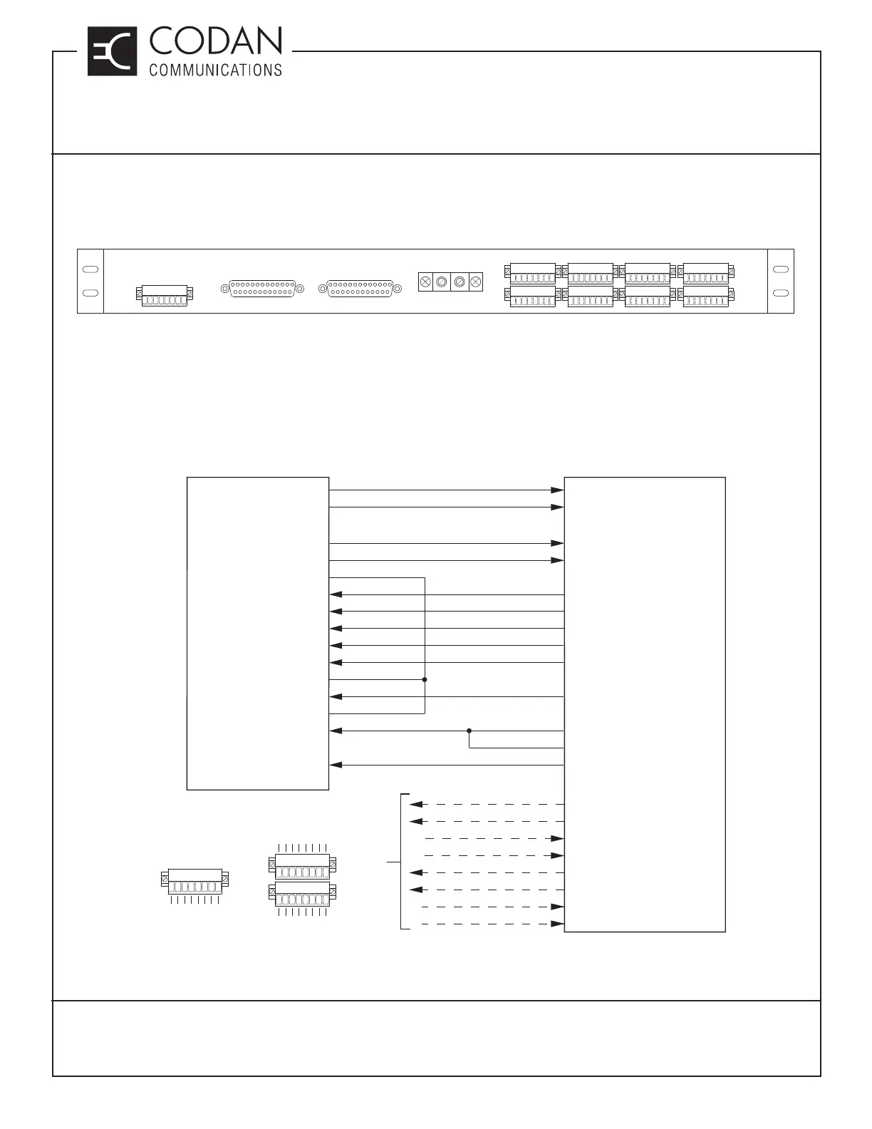
Installation:
In addition to the RJ45 interconnect cables on the front panel, the +9.5 Vdc power and ground must be connected
on the back panel. Figure 1 shows a diagram of the back panel of the CI-RC-4M-G2.
Figure 1:CI-RC-4M-G2 Back Panel
A female DB25 connector on the back of the subrack (J12) can be used for connectioning to the CI-RC-4M-G2
using a standard straight-through male-to-male DB25 cable. The A-PNL-AUX96-3 auxiliary connector can also be
used to connect to the CI-RC-4M-G2, as shown in Figure 2. The information in brackets is the function that uses
that particular connection. For example, if you are using CTCSS tones, the Rx Disc O/P must be connected. The
diagram only shows connections for Receiver and Transmitter A.
Figure 2: CI-RC-4M-G2 Connection Diagram
9.5VDC INPUT
+
-
CI-RC-4M-G2
AUX-E&M CONNECTIONS
ABCD
RX
TX
12345678
12345678
12345678
12345678
12345678
12345678
12345678
12345678
12345678
SUBRACK-1 A & B SUBRACK-2 C & D
CODAN RADIO EQUIPMENT
+9.5 Vdc
RXA Disc O/P
RXA BAL O/P1
RXA BAL O/P 2
TXA CSEL D0
TXA CSEL D2
+9.5 Vdc
RXA Disc O/P (CTCSS)
RXA Bal Audio 1 (DTMF and E&M)
TXA CSEL0 (Channel Selection)
TXA CSEL1 (Channel Selection)
TXA CSEL2 (Channel Selection)
E&M CONNECTIONS
Aux Bal Out 1
Aux Bal In 1
Aux Bal Out 2
Aux Bal In 2
CI-RC-4M-G2 MULTIPLE
LINK CONTROLLER
J9 +
B10 (J1-8)
B24 (J1-5)
A24 (J1-6)
C21 (J2-1)
B21 (J2-2)
A21 (J2-3)
TXA CSEL D1
TXA CSEL3 (Channel Selection)
TXA BANK A/B (BankSelection)
TXA Bal Audio 1 (E&M)
TXA CSEL D3
BANK A/B
GND
TXA BAL I/P 1
TXA BAL I/P 2
GND GND
TXA PTT TXA PTT (E&M)
Aux COR E
Aux COR C
Aux PTT A
Aux PTT K
J9 -
C23 (J2-4)
B9 (J6-1)
A32 (J4-1)
C18 (J1-1)
B18 (J1-2)
BB6 (J1-3)
RXA Mute
ACK PTT (Ack Tone)
RXA Mute (Simplex Operating Mode)
AUX - E&M CONNECTIONS
12345678
12345678
12345678
TX Bank A/B
COR Input
Rpt_Dis (A only)
Ground
RX Disc Out
RX Bal Audio 1
Ack PTT
RX Mute
TX Csel 0
TX Csel 1
TX Csel 2
TX Csel 3
Aux PTT Out
TX Bal Audio 1
TX PTT
GP O/P
A, B, C and D
Aux PTT K
Aux PTT A
Aux Bal In 2
Aux Bal Out 2
Aux Bal Out 1
Aux COR E
Aux Bal In 1
Aux COR C
RX
TX
Back Panel Pin-Out