Installing In-Sight
®
1720 Series Wafer Readers
33
5.2.2 Breakout Port Pin Assignments
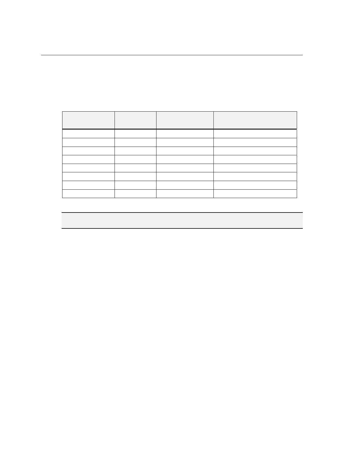
Table 5-3 lists the pin assignment for each of the 8 signal lines of the Breakout Port (labeled
“24VDC”) according to each method of access.
Table 5-3: Breakout Port Pin Assignments
In-Sight Breakout
Port Pin
Signal
Breakout Cable
Wire Color
Breakout Module* Terminals
1 +24VDC White/Green 6, 8, 10, 12, 14, 15, 16 (+24V)
2 Trigger + Green 5 (TRG+)
3 Trigger – White/Orange 4 (TRG-)
4 CTS Blue RS-232 serial (9-pin DSUB connector)
5 RTS White/Blue RS-232 serial (9-pin DSUB connector)
6 Serial Receive Orange RS-232 serial (9-pin DSUB connector)
7 Serial Transmit White/Brown RS-232 serial (9-pin DSUB connector)
8 Ground Brown 1, 2, 3 (GND)
*Refer to the In-Sight Breakout Module Installation and Reference (P/N 597-0008-xx) for more detailed information.
NOTE Unused bare wires can be clipped short or tied back using a tie made from non-conductive material.
Keep all bare wires separated from the +24VDC (White/Green) wire.
 Loading...