5
SECTION 2: INSTALLATION
OPTION SWITCH SETTINGS
BA30 bill acceptors contain an option switch bank on the
main logic board which allows the unit to be customized
to the requirements of the individual account. This switch
bank is factory set with switches 3 and 8 in the ON
position and 1, 2, 4, 5, 6 and 7 in the OFF position.
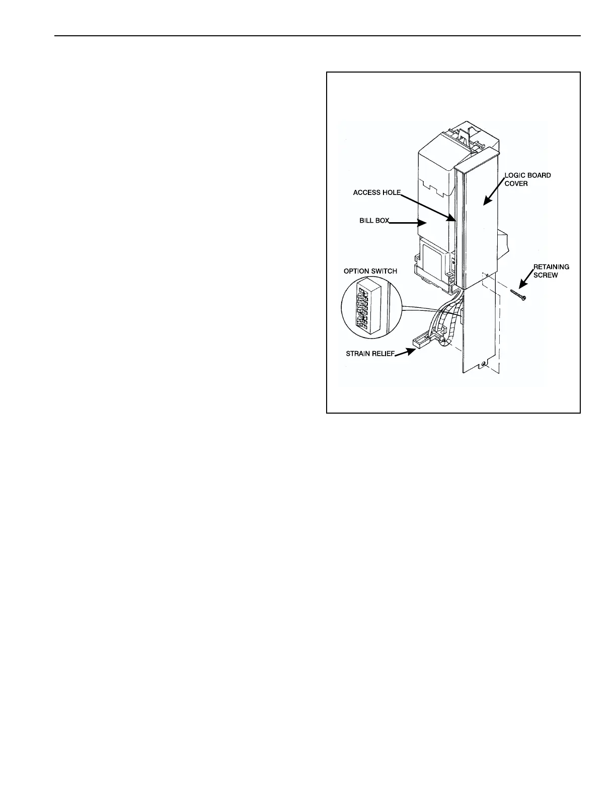
Setting Option Switches (see Figure 1)
For units manufactured without an access hole in the
logic board cover: Remove power from the bill accep-
tor. Remove the retaining screw that secures the main
logic board and strain relief. Carefully slide the main
logic board and strain relief from the cover. Allow the
strain relief to disengage the logic board and continue to
slide the logic board down until the option switch bank is
accessible. Set the option switches as desired. Reas-
semble the bill acceptor in the reverse order of disassem-
bly. Apply power and test for proper operation.
For units manufactured with an access hole in the
logic board cover: Removed power from the bill accep-
tor. Remove the bill box. Located on the side of the logic
board cover is a clear decal seal which covers the option
switch access hole. Carefully remove this decal seal to
access the option switch bank. Insert a small screwdriver
through the access hole to set the option switches as
desired. Place the decal seal back over the access hole
and reinstall the bill box. Apply power and test for
proper operation.
Figure 1