Page 28 800 Series
SECTION 5: TROUBLESHOOTING
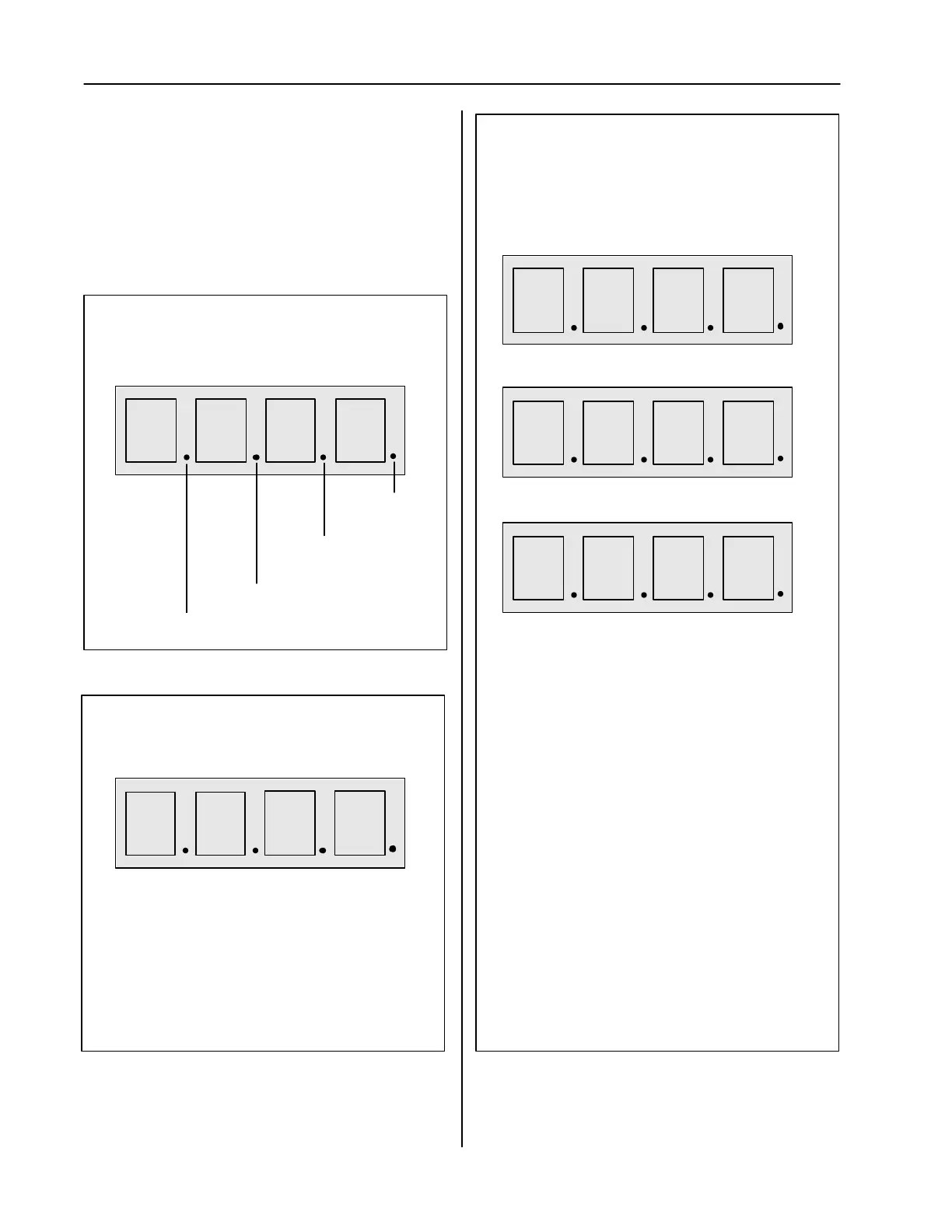
DIGITAL DISPLAY - DIGITS
(When Coin Is Inserted)
The Following Values In The Following Positions
Indicate a Response to the Coin that was Just
Dropped (the digit “2” is used for example purposes
only):
- -
-- = Coin Type Not Recognized
-2 = Coin Type Recognized but Not credited*
C - 0 2
0 2
2 = Coin Type Recognized and Credited
Figure 13
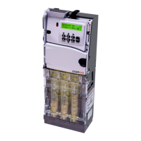
DIGITAL DISPLAY - DECIMALS
(When Coin Return Lever Is Depressed)
Indicates Right Cashbox Sensor Is Blocked
Indicates Float Level Set On At
Least One Tube
Indicates Power
Is ON
Indicates Left Cashbox Sensor Is Blocked
8 8 8 8
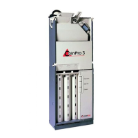
DIGITAL DISPLAY - DIGITS
(When Coin Return Lever Is Depressed)
Figure 14
TUBE A TUBE B TUBE C TUBE D
The Following Values In The Above Tube Positions
Indicate the Condition in the Corresponding Tube:
0 = No Sensors Are Blocked
1 = Lower Sensor Is Blocked
2 = Lower and Upper Sensors Are Blocked
8 = Tube Is Jammed
9 = Sensor Error
8 8 8 8
*Note: One of the following letter codes may
appear in lieu of the “C”
n An attempt has been made to route, however
the coin was not sensed at the credit allocation
sensors
C Rejected as controller has disabled acceptance
of the MDB coin type associated with this coin
or error in routing due to cashbox sensor being
blocked
d Rejected as coin has been disabled by the
acceptors internal coin enable settings
U Rejected as the coins value is too large to
enable coin’s acceptance or the value is too
small and the remainder system is disabled
t Rejected as the coin set associated with this
coin is not enabled
Figure 15
Diagnostics
When the coin return lever is depressed or a
coin is dropped, both the decimals points (Fig-
ure 13) and the four digits (Figures 14 and 15)
are used to communicate various diagnostic
conditions as shown: