IGS-NT Combi, SW Version 3.0, ©ComAp – May 2013
IGS-NT-Combi-3.0 Reference Guide.PDF
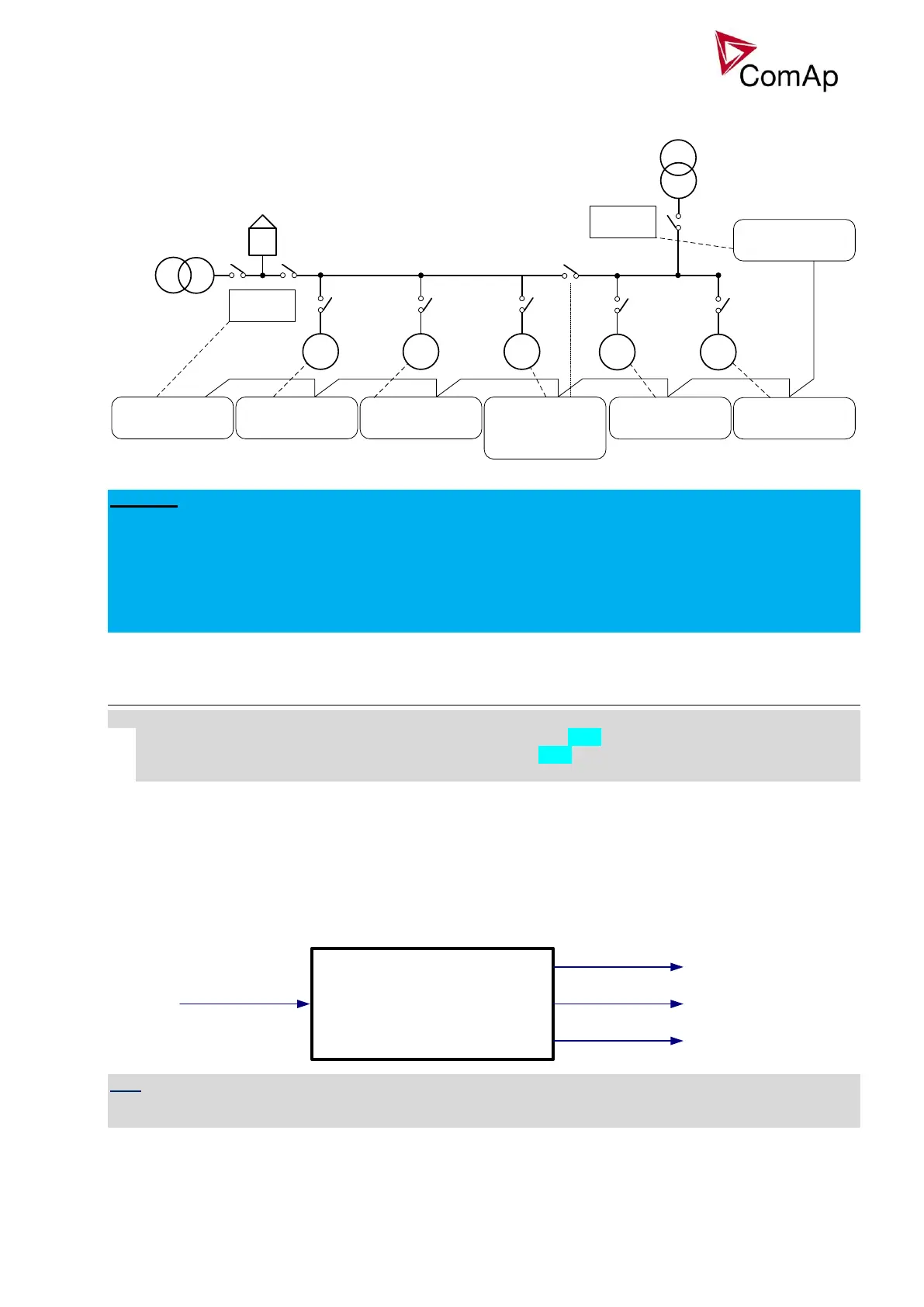
Important setpoints: Control group, GroupLinkLeft, GroupLinkRight
G1 G2 G3
Basic settings:
Contr. Addr = 2
Pwr management:
Control group = COMMON
Basic settings:
Contr. Addr = 1
Pwr management:
Control group = COMMON
Basic settings:
Contr. Addr = 3
Pwr management:
Control group = COMMON
GroupLinkLeft = COMMON
GroupLinkRight = 2
BTBfeedback = GroupLink
Basic settings:
Contr. Addr = 6
Pwr management:
Control group = COMMON
InteliMains
CAN
G4 G5
InteliMains
Basic settings:
Contr. Addr = 4
Pwr management:
Control group = 2
Basic settings:
Contr. Addr = 5
Pwr management:
Control group = 2
Basic settings:
Contr. Addr = 7
Pwr management:
Control group = 2
Figure: Power management using control groups
EXAMPLE:
In the example above, bus tie breaker separates gen-sets into two groups. BTB is operated manually in this
example. If BTB is opened, each control group is working independently. If the BTB closes, controller
number 3 sends signal via CAN bus and groups COMMON and 2 are connected together. One InteliMains
(the one with lower CAN address) takes over and controls both groups. It is not possible to use both
InteliMains parallel to the Mains when BTB is closed and InteliMains with lower CAN address takes over the
control. In this case gen-sets are controlled only by this InteliMains and the second InteliMains does not have
any means to control its parallel function.
Load shedding
All LOAD SHED outputs are activated (closed) to trip the unessential load when gen-set goes to island:
a) When GCB is closed after mains fail and gen-set starts in SEM / AUT mode.
b) When MCB opens from parallel to mains operation in SEM / AUT mode.
c) Before MCB is opened in MAN mode by button.
The load shedding function is active in all controller modes except OFF.
Load shedding has three steps and each step is linked with its own Load shed x binary output. There is only
one load shed level and delay for all three steps as well as recon level and delay. Load shed can only move
from one step to the next, e.g. No LoadShed to LdShed S1 to LdShed S2 to LdShed S3 and vice versa.
If manual reconnection of the load is desired, the AutoLd recon setpoint needs to be disabled (AutoLd recon
= DISABLED) and the MAN load recon binary input needs to be configured.
Rising edge on this input resets the controller to a lower stage, but only if the load is under the Ld recon level
at that moment.
Load shedding: Ld shed level
Ld shed delay
Ld recon level
Ld recon delay
AutoLd recon
LdShed stage 1
LdShed stage 2
LdShed stage 3
ManualLdRecon
HINT
If no Load Shedding outputs are configured, there is no record to history and no scrren timer indication of the
activity of this function.