IGS-NT-BC, SW Version 1.2.0, ©ComAp – January 2019
IGS-NT-BC-1.2.0 Reference Guide.PDF
This input is used to activate the load reserve set #2 instead of the set #1, which
is active by default. The set #2 is adjusted by setpoints:
• #LoadResStrt 2 and #LoadResStop 2 if the power management is
switched to absolute mode
• #%LdResStrt 2 and #%LdResStop 2 if the power management is
switched to relative mode.
CAUTION!
All controllers cooperating together in Power management must have the same
load reserve set selected.
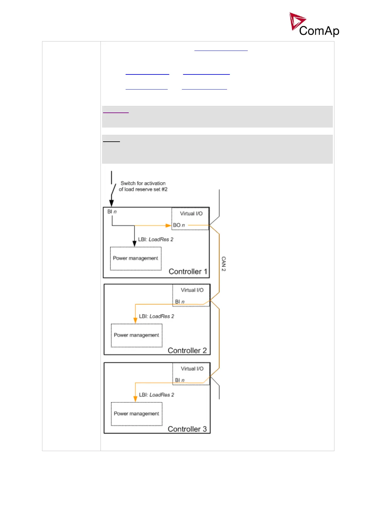
NOTE:
It is possible to use virtual peripheries for distribution of the binary signal from one
physical switch connected to one controller to all other controllers over the CAN
bus.
EXAMPLE OF USING VIRTUAL PERIPHERIES FOR SIGNAL DISTRIBUTION