IGS-NT-BC, SW Version 1.2.0, ©ComAp – January 2019
IGS-NT-BC-1.2.0 Reference Guide.PDF
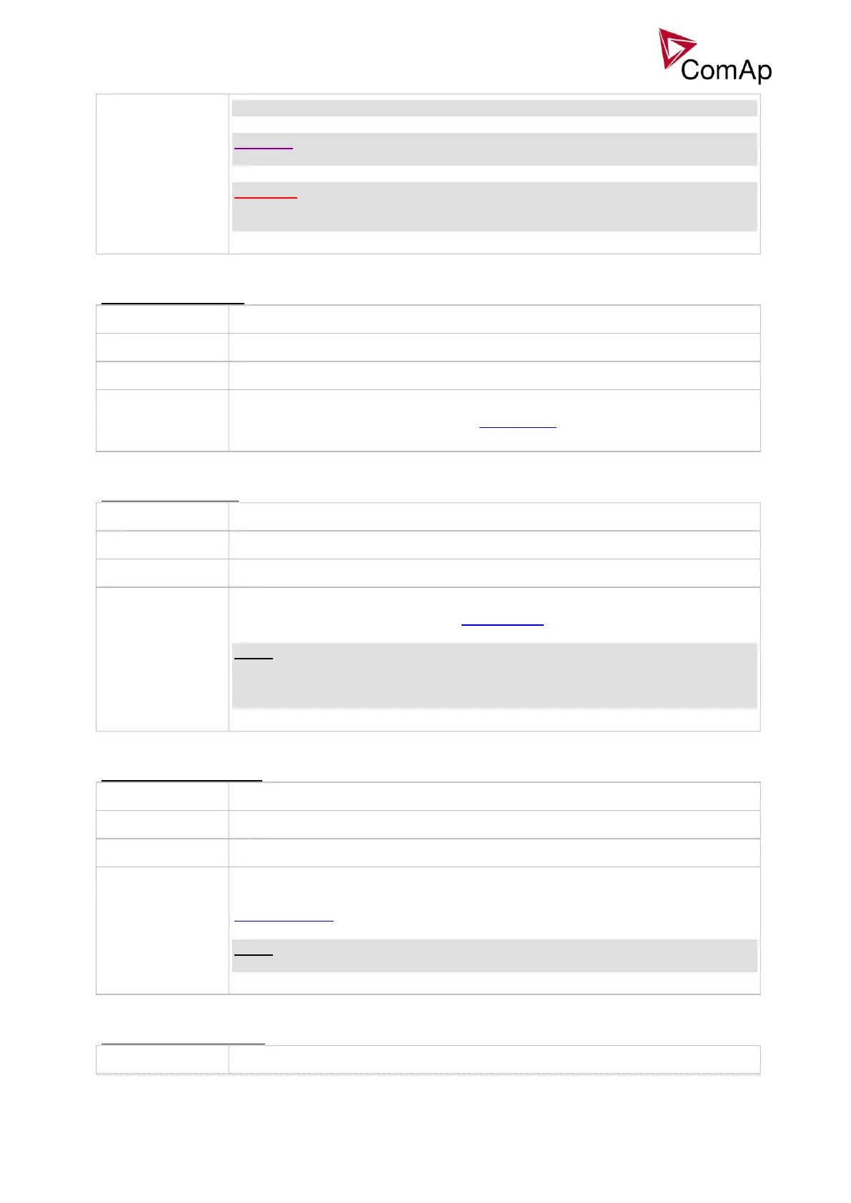
correct generator current readings.
CAUTION!
The maximum measurable input current to the controller current terminals is 11A.
WARNING!
Do not discconnect the CT terminals from the controller while there is nonzero
current in the CT primary circuit!
Nominal current of the primary side of the generator current transformers. The
secondary side is adjusted by setpoint CT ratio sec.
Nominal current of the secondary side of the generator current transformers. The
primary side is adjusted by setpoint CT ratio prim.
NOTE:
The CT secondary nominal current is adjustable only in IG-NTC and IS-NT. The
IG-NT has the CT secondary nominal current adjusted fixedly to 5A regardless of
this setpoint.
Nominal current of the primary side of the current transformer connected to the
controller terminals labeled IN. The secondary side is adjusted by setpoint
EarthFltCurCTs.
NOTE:
The IN terminals are used for measurement of earth fault current.