IGS-NT Combi, SW Version 3.0, ©ComAp – May 2013
IGS-NT-Combi-3.0 Reference Guide.PDF
Controller Redundancy
Redundant system is a general term for applications where there are two controllers at each gen-set. One is
the main controller, which controls the gen-set in normal conditions, the other is the redundant controller,
which takes over the control when the main controller fails. Both controllers have identical firmware and most
of the configuration and setpoints. Only several things need to be adjusted/configured differently because of
the rendundancy function itself.
CAUTION!
If there are shared binary or analog outputs used on controller (e.g. for system start/stop), it is necessary to
prepare the configuration in the way so each controller uses binary or analog output set with different
address. Configuration in gen-set controllers then needs to be altered so it can receive signals from both
controller controller (e.g. using built-in PLC functions).
Redundant systems using binary signals
It is not possible to use this redundancy system since correct function of controller depends on CAN bus
communication and thus CAN redundancy should be always used.
Redundant systems using CAN bus
This system uses the CAN bus for detection whether the main controller is operational or not. If the
redundant controller has not received two consequent messages from the main one (~100ms) it will take
over the system control - it activates the binary output CTRLHBEAT FD, which has to be wired in such a way,
that it disconnects the dead main controller from the control, connects the redundancy controller instead and
activates it by deactivation of the binary input EMERG. MANUAL.
As there can be up to 16 pairs of controllers at the CAN bus it is necessary to select which main controller
(address) belongs to which redundant one. The setpoint ProcCtrlSingle:Watched Contr is used for this
purpose. It must be adjusted to address of the respective main controller in each redundant controller and it
must be adjusted to 0 in each main controller.
CAUTION!
Correct wiring of all inputs and outputs that should be used both by the main and the redundant controller
needs to be done. Please refer to the corresponding chapter for wiring of binary inputs and outputs.
Do not use Shared Binary Inputs/Outputs for CTRLHBEAT FD -> EMERG.MANUAL connection since the failed
controller may not interpret it correctly!
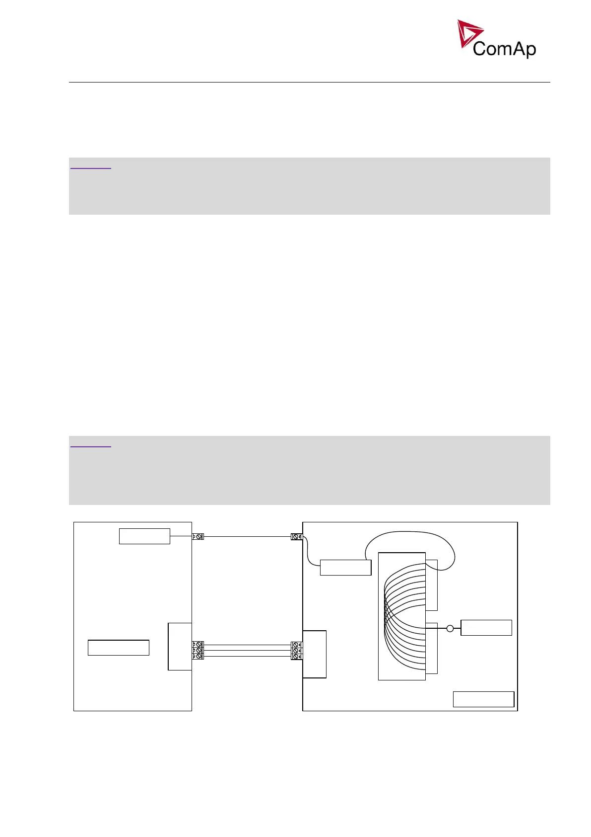
VPIO
VPI
VPO
CtrlHBeat FD
Emerg. manual
CAN
LOG BOUT
LOG BIN
Watched contr = X
Setpoint
Emerg. manual
LOG BIN
CAN
BOUT
BIN
LOG BIN
MAIN CONTROLLER
REDUNDANT CONTROLLER
Contr. Address = X
Setpoint
Figure: Example of redundancy function
In the figure above the signal of logical function CtrlHBeat FD is used to disable the main controller if it is lost
from CAN bus or CAN bus communication from that controller becomes erratic. It is used also to disable the
redundant controller when the communication on CAN bus is alright (it is negated). For more information on