INSTALLATION GUIDE FOR mBDA OD SERIES
Copyright - refer to title page
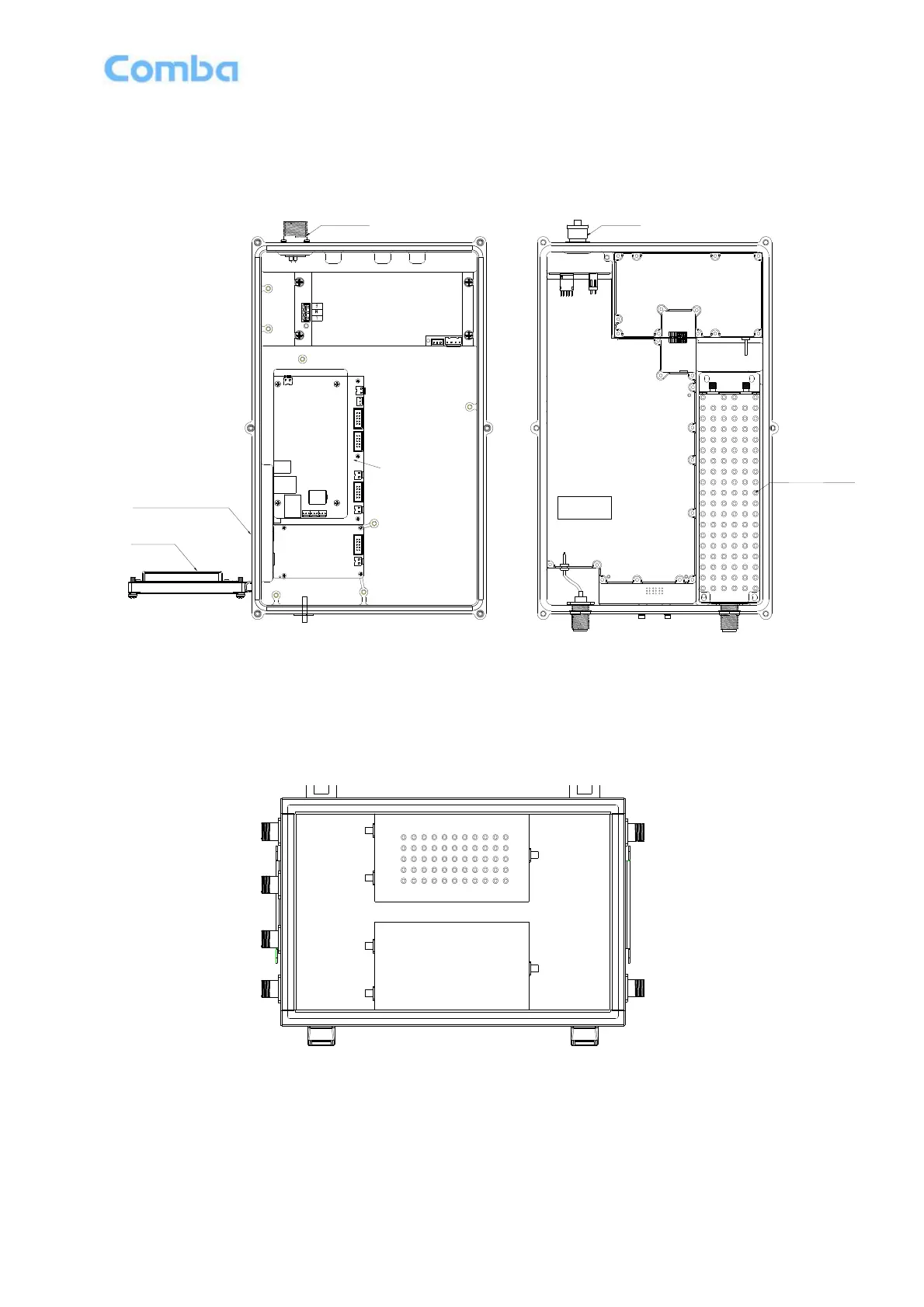
2.2 EQUIPMENT LAYOUT
Shown below is the internal layout of the mBDA.
RS485
POWER
MODEM/LAN
(Optional)
Distribution
Board
(above
Distribition Board)
MODEM
DT
MT
DT
RF OUT
RF IN
U_RF IN
Bottom
DL PA
Digital
Integrated
Module
Cover
UL PA
PSU
MCU
RX
TX
Duplexer
Li-ion Battery
(Optional)
Operation Window
Figure 5: Layout of the mBDA
Note: When dual-band mBDA is required, these also need a second unit. The second unit does not need a
MODEM board and modem antenna connector/LAN connector. And the second unit is ordered separately.
Figure 6: Layout of the mBDA Combiner Unit
Note: When dual-band mBDA is required, these also need a Combiner unit. And the Combiner unit is
ordered separately.