INSTALLATION GUIDE FOR mBDA OD SERIES
Copyright - refer to title page
0.2 INDEX TO FIGURES AND TABLES
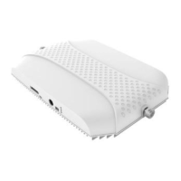
Figure 1: Front, Side and Bottom Views of the mBDA Enclosure ............................................................. 10
Figure 2: Front, Side and Bottom Views of the dual-band combiner Enclosure ........................................ 11
Figure 3: mBDA Functional Block Diagram ................................................................................................ 12
Figure 4: Dual-band mBDA System Diagram ............................................................................................ 12
Figure 5: Layout of the mBDA .................................................................................................................... 13
Figure 6: Layout of the mBDA Combiner Unit ............................................................................................ 13
Figure 7: Mounting Rack Overview ............................................................................................................ 19
Figure 8: Install Mounting Rack1 ................................................................................................................ 20
Figure 9: Install Mounting Rack2 and Mounting Rack Bolt ........................................................................ 20
Figure 10: Hand up the mBDA ................................................................................................................... 21
Figure 11: Finish Installation ...................................................................................................................... 21
Figure 12: Install Mounting Rack Bolt ......................................................................................................... 22
Figure 13: Install Mounting Rack2 .............................................................................................................. 22
Figure 14: Hand up and Secure the second mBDA ................................................................................... 22
Figure 15: Finish Installation ...................................................................................................................... 23
Figure 16: Equipment Connectors ............................................................................................................. 24
Figure 17: Operation Window .................................................................................................................... 25
Figure 18: Combiner Connectors ............................................................................................................... 25
Figure 19: Communication Cable connection ............................................................................................ 27
Figure 20: Communication Cable connection ............................................................................................ 27
Figure 21: Battery Connection in Operation Window ................................................................................. 28
Figure 22: OMT Connection without Chassis Open ................................................................................... 28
Figure 23: RFU LEDs on Outer Window .................................................................................................... 29
Figure 24: Input IP Address ........................................................................................................................ 32
Figure 25: Input Domain Name .................................................................................................................. 32
Figure 26: Input User Name and Password ............................................................................................... 32
Figure 27: Web GUI Main Screen .............................................................................................................. 33
Figure 28: [Devices] Screen ....................................................................................................................... 33
Figure 29: Main Control Unit ...................................................................................................................... 34
Figure 30: RF Unit ...................................................................................................................................... 34
Figure 31: RF Unit Detail Information ......................................................................................................... 35
Figure 32: [Commissioning] Screen ........................................................................................................... 35
Figure 33: [Firmware] Screen – MCU Firmware Upgrade .......................................................................... 36
Figure 34: [Firmware] Screen – Module Software Upgrade ....................................................................... 36
Figure 35: [Firmware] Screen – Pop-up Window 1 .................................................................................... 36
Figure 36: [Firmware] Screen - Swap......................................................................................................... 37
Figure 37: [Management] Screen ............................................................................................................... 37
Figure 38: Management – Import & Export ................................................................................................ 38
Figure 39: Management – IP Setting .......................................................................................................... 38
Figure 40: Management – Comm. Setting ................................................................................................. 39
Figure 41: New Site Report is for easy monitoring set up .......................................................................... 39
Figure 42: Management – Security ............................................................................................................ 40
Figure 43: Modify Password ....................................................................................................................... 40
Figure 44: Management – Device Reset .................................................................................................... 40
Figure 45: Management – PA Reset .......................................................................................................... 41
Figure 46: Management – Device Info ....................................................................................................... 41
Figure 47: Management – Isolation ............................................................................................................ 42
Figure 48: Management – Report .............................................................................................................. 42
Figure 49: Commissioning Procedure - Start ............................................................................................. 43
Figure 50: Commissioning Procedure – Site Info. Setting ......................................................................... 43
Figure 51: Dev Info & Date/Time ................................................................................................................ 44
Figure 52: Commissioning Procedure – Isolation Detective ...................................................................... 44
Figure 53: Commissioning Procedure – Isolation Detective Confirm ......................................................... 45
Figure 54: Commissioning Procedure –Isolation Detection Failed ............................................................ 45
Figure 55: Commissioning Procedure –Isolation Detection Finish ............................................................. 45
Figure 56: Commissioning Procedure – Sub-band bandwidth and Switch Setting .................................... 46
Figure 57: The Protective Frequency Edge Interval (GSM system) ........................................................... 46
 Loading...