Page 16
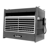
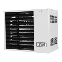
UNIT HEATER
2.1 Gas Controls - Automatic Ignition
The heaters may be fitted with one of two types of gas control valves dependent upon the model, each
giving the same control elements as follows (see Section 4).
2.1.1 Main Gas Burner
The multifunctional main gas valve contains a gas regulator and two automatic shut off valves. When
set up as defined in Section 4 the valves will have a step opening operation on the main gas to give
smooth lighting. Settings of the valves are given in Section 4 and tables in Section 2.
2.1.2 Start Gas Burner
There is one solenoid valve to control the pilot burner gas supply which is designed to operate at inlet
pressure and therefore does not need a regulator.
2.2 Gas Controls - Manual Ignition
The multifunctional gas valve contains a main gas regulator, a safety gas valve controlled by the
thermocouple, and a solenoid valve to operate the main gas.
The manual control knob and Piezo electric igniter incorporated in this control allow for the safe
manual ignition of the pilot and selection for automatic operation of the main burner.
2.3 Main Fan
The main air moving fan(s) fitted to these heaters are operated automatically by the fan thermostat
within the Honeywell combination fan/limit thermostat. When suitably connected to site wiring (see
Section 5) the fan(s) may also be used for distributing unheated air.
2.4 Limit Thermostats
There are two limit thermostats on these heaters to protect them from overheating, should the fan fail
for any reason. One is within the Honeywell combination thermostat and the second is situated on the
side of the heater towards the rear. Note: on models 340 and 380 B & C versions there is an extra
secondary limit thermostat protecting the third fan unit.
2.4.1 Honeywell Combination Fan/Limit Thermostat
The combination fan/limit thermostat is a dual function control and safety device (see Fig. 2.7). There
are two of these fitted to CUHD versions, the second one on the inlet spigot at the rear of the heater.