Page 58
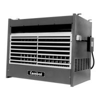
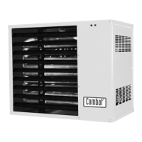
UNIT HEATER
7.6 CUHB & CUHC Centrifugal Fan/Guard/Motor Assembly
The direct drive fan/s for the CUHB & CUHC range is supplied as a complete assembly and therefore
does not need to be disassembled. Each fan is fitted to the rear of the cabinet secured with four fixing
screws and washers.
7.6.1 To Remove the Fan(s)
Disconnect the electrical connections from the terminal block at the rear of the heater making a careful
note of the positions of the connecting wires and identifying the current speed setting.
Remove the fan / motor assembly by removing the fixing screws whilst supporting the weight of the
fan (approx. 19 kg) and making a careful note of the fan orientation.
For the CUHC versions fitted with an inlet spigot assembly the fan/s may be accessed through the
removable covers on the sides, top and bottom of the spigot, as required.
7.6.2 To Refit the Fan(s)
To reassemble reverse the above ensuring that the correct motor connections are used as identified
when disconnecting and that new rubber seal is used between the fan flange and the heater rear panel.
It is important that the fan is fitted to the rear panel in its correct orientation with the curved surface
upwards.
It is most important that the colour code of the fan wires is strictly observed to ensure correct operation,
and being careful to use the correct neutral connection. The Blue Neutral is for the main fan; the Blue/
White neutral is for the burner controls and must not carry the load of the main fan .This is because the
burner electrical supply is protected from mains bourne interference by the use of a special conditioning
filter which is not capable of carrying the full load of the main fan.
Check that the fan blades are free to rotate without catching before turning on the power to the fan.
The three speed winding connections are:
Low speed: White N, Red Live The other two windings are "parked" separately in spare terminals
Medium speed: White N, Blue live. The other two windings are "parked"separately in spare terminals
High speed: White N, Black live. The other two windings are "parked" separately in spare terminals
7.7 Combination Fan/Limit Thermostat
7.7.1
To gain access to this thermostat, remove the cover retaining screw and pull of the cover.
7.7.2
Disconnect the electrical connections by pushing in with a small screwdriver and pulling out the wires.
(see Fig. 2.8).
The earth wire is held under a screw connection.