Page 50
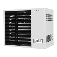
UNIT HEATER
6.2 Fan/Motor Assembly all Models
The main fan requires very little maintenance as the bearings are sealed for life and need no lubrication.
If the fan blades need cleaning remove the fan guards and use a small brush or duster to clean the fan
blades from each side of the fan(s).
6.2.1 For CUHB & CUHC Centrifugal Fan Models
CUHB and CUHC models are fitted with thermally protected three speed direct dive fans. The data
table indicates the normal number of fans and their standard running speed for each model .They
require very little servicing other than cleaning of the fan blades.
It is essential that the fans are not operated at higher speeds than the original setting on the heater
without prior consultation with Combat Engineering Ltd. Such action may cause the fan motors to be
overloaded.
Overloading the motor will cause the built in thermal overload protection device to operate.
Where two or three fans are fitted they must be all operating at the same speed and they will be
switched using a fan contactor built into the heater see the wiring diagrams.
The "HIGH" speed option is available to give the normal required air flow against higher static pressures
and is not intended to be operated free blowing or against low resistance. Use of the fans under these
conditions may cause the fan thermal overload to operate and the fan thermostat to cycle due to a lower
temperature rise.
The three speed winding connections are:
Low speed: White N, Red Live The other two windings are "parked" separately in spare
terminals
Medium speed: White N, Blue live. The other two windings are "parked" separately in spare terminals
High speed: White N, Black live. The other two windings are "parked" separately in spare
terminals
For CUHC models the fans may be accessed via the removable panels in the top, bottom and sides of
the inlet spigot compartment as required.
6.3 Heat Exchanger
The heat exchanger should remain clean unless some problem has developed with combustion. However,
an inspection of the condition of the heat exchanger is well worth while especially looking for signs of
overheating at the lower edges with may indicate burner over firing or persistently low air flows. Any
deposits in the heat exchanger may be removed with a small flue brush and vacuum cleaner from the
burner compartment after first removing the burner tray.