Page 55
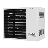
UNIT HEATER
7.3.1 Removal of pilot burner
i) Remove the rear lower panel of the heater.
ii) Unscrew the pilot gas pipe at its compression fitting with the pilot gas valve or main gas valve as
appropriate.
iii) Unplug the H.T cable from the Piezo electric igniter or spark generator, as appropriate.
iv) Either unplug the flame probe from its jack socket or unscrew the thermocouple from the gas
valve.
v) Using a 10mm spanner undo the two set screws securing the pilot bracket assembly to the main
burner manifold.
The assembly will now come free by pushing it slightly forward and then allowing it to drop so that it
will pull clear of the main burner .
7.3.2
Using the appropriate spanners undo the thermocouple /flame probe, ignition electrode and gas pipe
from the rear of the ignition burner.
7.3.3
To replace directly reverse the above.
All manual ignition models use the S.I.T Nova multifunctional valve for main gas and pilot gas control.
Electrical connection is by a plug on a flying lead.
There are also ¼" receptacles for the connection of the thermocouple interrupter.
NOTE: It is important that the correct injector is used and that when assembling the gas pipe to the
pilot burner that the injector is fitted onto the special compression nut so that as the gas pipe is withdrawn
the injector is drawn out of the burner.Failure to fit the injector correctly will cause gas leaks and
permanent damage to the injector.
The Ignition electrode has a small tag connector for connecting the H.T/lead and ALWAYS fits into the
centre hole of the pilot burner.
The thermocouple or flame probe (with permanently connected P.T.F.E. insulated wire) is fitted in the
end hole of the pilot burner
7.4 Gas Control Valves
7.4.1
The gas control valves of all heater types are accessible from the rear of the heater without further
disassembly or may be withdrawn as part of the burner assembly as convenient.
These instructions assume that the valves are removed with the burner tray remaining in place.
Section 2 tables give details of the gas valve specified for use on the various options available.
IT IS MOST IMPORTANT THAT ONLY THE CORRECT GAS VALVES SPECIFIED FOR
EACH MODEL TYPE ARE USED WHEN REPLACING THESE CONTROLS.