Page 21
UNIT HEATER
3.2 General
All models must be installed with the base level and may be suspended from above or from specially
prepared wall brackets of sufficient strength to adequately support the weight of the heater as listed in
Section 2. Data Tables. Drop rods should be a minimum of 10 mm diameter mild steel. The four
hanging brackets are located on top of the heater, for all models. All heaters may be mounted on a shelf
of NON combustible material.
Heaters will normally be installed at between 2.75m and 3.75m above the floor.
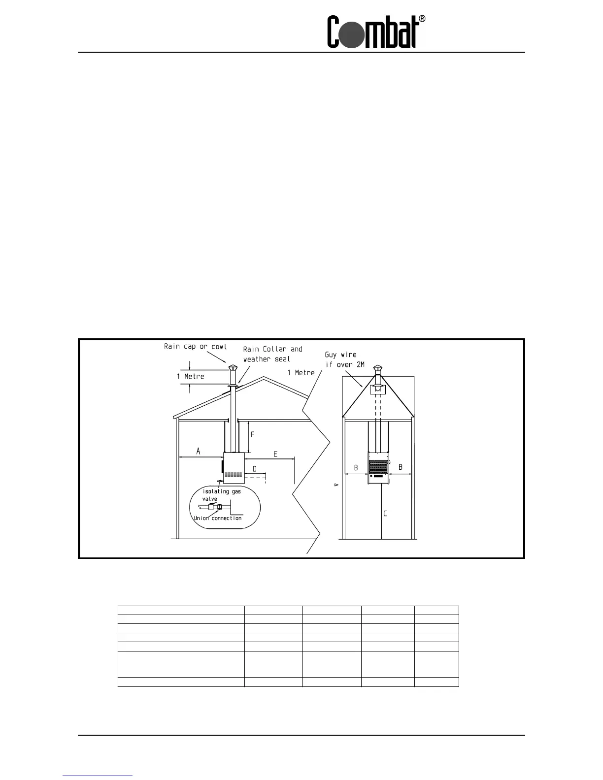
Clearances around the heater as indicated in Fig. 3. 1 must be maintained to ensure adequate access for
servicing and to ensure that the temperature of combustible materials does not exceed 65°C.
It is important to ensure that at all times there is adequate air circulation around the heater to supply air
for combustion ,ventilation and distribution.
Consideration should also be given when siting a heater to allow for the proper location of the flue .
It is important that the gas supply pipe and the electrical connections do not support any of the heaters
weight
Fig 3.1 Typical Installation
Clearance s for installatio n all mod els
CUHA.... CUHB... CUHC... CUHD...
"A " Re ar of fan to wall 0.6 M 0.6 M Se e Below Se e Below
"B " C le aran ce at side s 0.8 M 0.8 M 0.8 M 0.8 M
"C " He ight to base 2.75 to 3.0 M 2.75 to 3.75 M N /A N/A
Clearance in front of heater See Below See Below
"D " T o remove burner 1.1 M 1.1 M 1.1 M 1.1 M
"E" From combustible material 3.0 M 3.0 M N/A N/A
"F" Clearance above he ate r 0.6 M 0.6 M 0.6 M 0.6 M
CUHC & CUHD inlet and outlet ducts
D imension "A" Minimu m le ngth of inlet d uct 2 x large st d imen sion
Minimum length of outlet duct 1.1 m or 2 x largest dimension whichever is greater.