13
Programming buttons for intercom call
Example 1 - all systems (INCLUDING KITS!) - General intercom
on a monitor with user code 5, P2 programming = general internal call, P3 = general intercom with address 9
Example 2 - Selective intercom
on a monitor with user code 1 and intercom address 1, P2 programming = selective intercom with address 2, P3 = selective
intercom with address 3
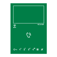
1. Set S2 DIP switches 6 to the combination 1.
» the privacy LED
flashes.
S2 DIP
1 2 3 4 5 6
0 0 0 0 0 1
S2
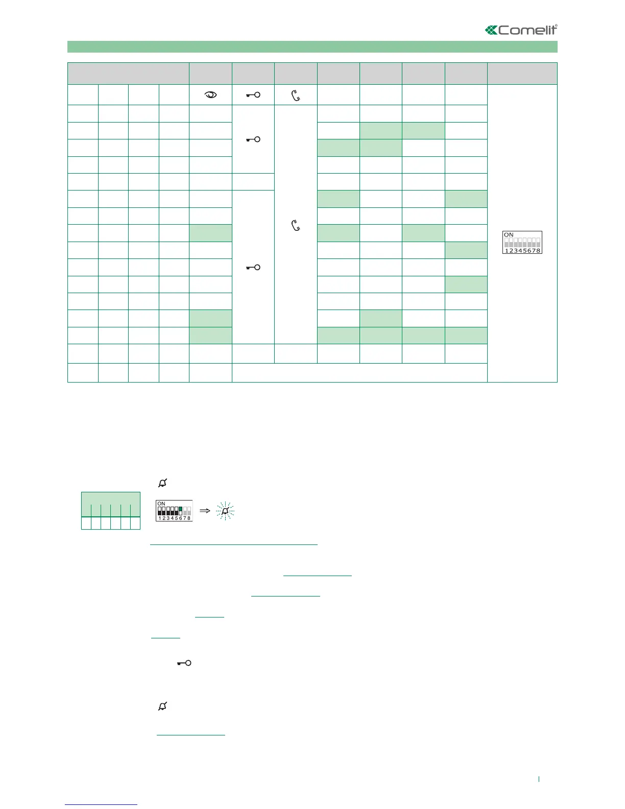
2. Refer to the table “Programming buttons for intercom call” and select a combination in which the intercom function
(either INT or INTb) is listed for the buttons you wish to program.
EXAMPLE 1: for P2= general internal call, set S2 DIP switches 1-2-3-4 to the combination 1000 or 0011 or 1011 (P2=INT)
or 0100 (P2=INTb) and set S1 with address 5 as per addressing table, then go to point 3
EXAMPLE 1: for P3= general intercom, set S2 DIP switches 1-2-3-4 to the combination 1110 or 1011 (P3=INT) or 1000
(P3=INTb) and set S1 with address 9 as per addressing table, then go to point 3
EXAMPLE 2: for P2= selective intercom, set S2 DIP switches 1-2-3-4 to the combination 1000 or 0011 or 1011 (P2=INT)
and set S1 with address 2 as table B, then go to point 3
EXAMPLE 2: for P3= selective intercom, set S2 DIP switches 1-2-3-4 to the combination 1110 or 1011 (P3=INT) and set S1
with address 3 as table B, then go to point 3.
3. Press and release the key to be associated with the function
» the lock-release LED
flashes 4 times.
» a confirmation tone will sound.
4. To exit programming mode, set S2 DIP switches 5-6 to the combination 00
» the privacy LED
switches o
5. When programming is complete, set S2 DIP switches 1-2-3-4 to the combination 1111. Restore the user code
setting on S1, see addressing table.
DIP S2 DIP S1
DIP 1 DIP 2 DIP 3 DIP 4
P1 P2 P3 P4
ADDRESS
0 0 0 0
1 0 0 0 INT INTb
0 1 0 0 INT INTb
1 1 0 0
0 0 1 0
1 0 1 0
INT INTb
0 1 1 0
1 1 1 0 INT INTb INT
0 0 0 1 INT
1 0 0 1
0 1 0 1 INT
1 1 0 1
0 0 1 1 INTb INT
1 0 1 1 INT INT INT INT INT
0 1 1 1
1 1 1 1 PROG