9
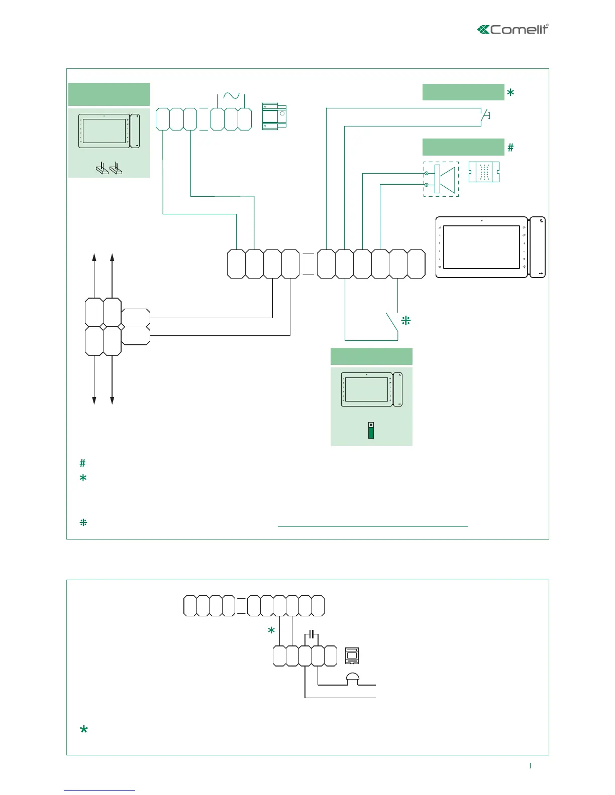
Connections
1212/B
0
2
0
0
3
2
0
ADDITIONAL POWER
SUPPLY (IF NECESSARY)
6801W
1214/2C
VIDEO ENTRY
SYSTEM RISER
VIDEO ENTRY
SYSTEM RISER
+
-
1
P
F
C
2
P
F
C
1
IN IN
2
+
S
-
S
FLOOR DOOR CALL
ADDITIONAL RINGER
1229
CV1CV2
LM
LM
OUT
L
IN
L
IN
L
OUT
L
PROGRAMMABLE INPUT
CV6
A
B
LL
20 m MAX - Connect only one call repetition device for each user code.
20 m MAX - Use shielded cable for the connection and do not route the cables in the vicinity of heavy inductive loads
or power supply cables (230V/400V).
Where multiple door-entry phones or monitor backplates have the same user code, connect the CFP button on one
only; all the devices will ring simultaneously.
For the programming procedure, see paragraph: LED/alarm/lock-release/actuator programming.
20 m MAX - Connect only one call repetition device for each user code. If inductive loads are connected, the
connection of 470nF capacitance in parallel with the C-NO contacts of Art. 1122/A is advisable.
Variant: connection of call repetition device Art. 1122/A