34
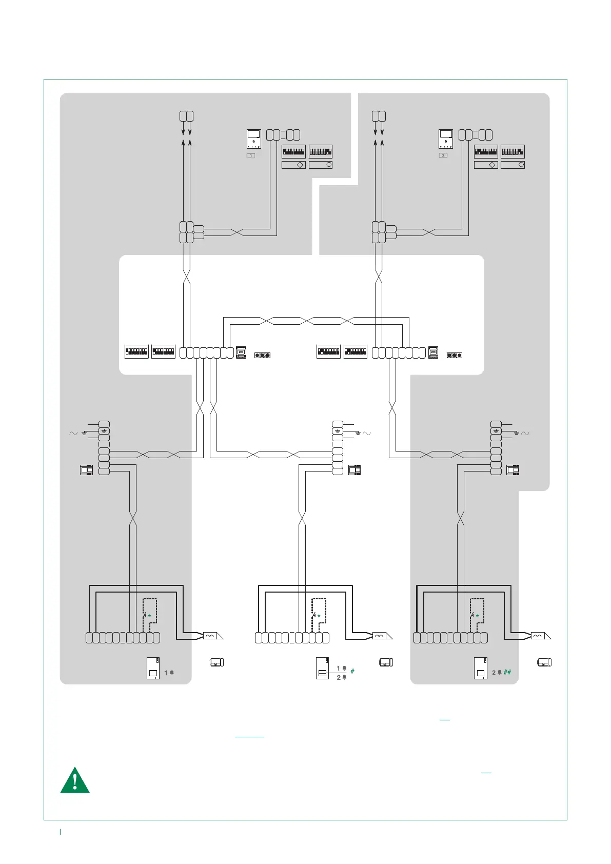
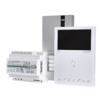
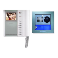
Wiring diagram for system with 2 single-family KITS KIT 8461V and main external unit Art.
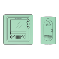
4893
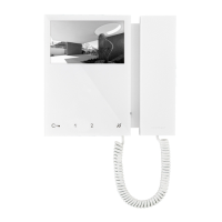
8461V8461V
LL
O
D
E
T
R
NO
SE
-
SE
+
NC C
M
O
C
1209
L
N
110-240V
L2
L2
L1
L1
4893
1404
L
M
L
M
L
S
L
S
LP
IN
MAX
ON
85 764321
MIN
ON
85 764321
LP
OUT
A
B
JP1
LL
O
D
E
T
R
NO
SE
-
SE
+
NC C
M
O
C
4893
L
N
110-240V
L2
L2
L1
L1
1209
LL
O
D
E
T
R
NO
SE
-
SE
+
NC C
M
O
C
4893
ON
85 764321
12 34 675 8
ON
C
F
P
LL
C
F
P
1
2
LM
LM
OUT
L
IN
L
IN
L
OUT
L
1214/2C
LL
1404
L
M
L
M
L
S
L
S
LP
IN
MAX
ON
85 764321
MIN
ON
85 764321
LP
OUT
A
B
JP1
ON
85 764321
12 34 675 8
ON
C
F
P
LL
C
F
P
1
2
LM
LM
OUT
L
IN
L
IN
L
OUT
L
1214/2C
LL
L
N
110-240V
L2
L2
L1
L1
1209
6721W
6721W/BM
6721W
6721W/BM
S1 S2
A
P
S1 S2
A
P
MNVK/017CQC
# To program the special function “buttons 1-2 enabled with call addresses 1-2” see page 11.
## To program the call address, see page 12 - 13.
*
Local lock release button.
The function “External unit (Porter) with switching (secondary)” is active by default (see page 26).
The door open indication function is not available.
The self-ignition function is available (with toggle function between 2 external units)