38
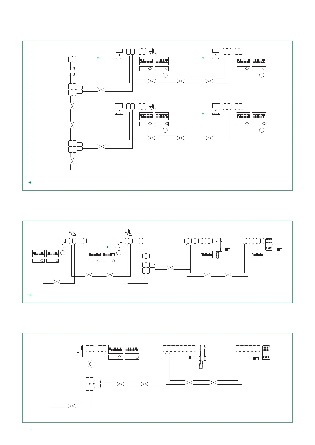
Connection diagram for system with maximum expansion in branch connection for single
call address
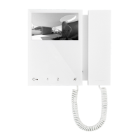
Connection diagram for cascade connection from internal video unit of additional door-
entry phones Art. 2610 and Art. 6228(B)(W)
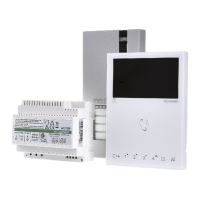
Connection diagram for branch connection from internal video unit of additional door-
entry phones Art. 2610 and Art. 6228(B)(W)
LL
1216
P
12 34 675 8
ON
12 34 675 8
ON
CV5
ON
85 764321
12 34 675 8
ON
LM
LM
OUT
L
IN
L
IN
L
OUT
L
1214/2C
LM
LM
OUT
L
IN
L
IN
L
OUT
L
1214/2C
C
F
P
LL
C
F
P
1
2
C
F
P
LL
C
F
P
1
2
1209
12 34 675 8
ON
12 34 675 8
ON
ON
85 764321
12 34 675 8
ON
C
F
P
LL
C
F
P
1
2
C
F
P
LL
C
F
P
1
2
6721W
6721W/BM
6721W
6721W/BM
+6710
6721W/BM
+6710
6721W/BM
+6710
6721W
6721W
S
SS
S1 S2
A
P
S1 S2
A
P
S1 S2
A
P
S1 S2
A
P
MNVK/Q22
Additional monitors Art. 6721W/BM do not include a backplate.
LM
LM
1214/2C
OUT
L
IN
L
IN
L
OUT
L
1216
L L
6228B
6228W
SW1
S2 S1
S
+
S
-
C
F
P
L L
C
F
P
ON
85 764321
12 34 675 8
ON
C
F
P
LL
C
F
P
1
2
1209
33
P C S
-
L L
C
F
P
C
F
P
S
+
2610
SW3
S2 S1
S1
ON
85 764321
S1
ON
85 764321
ON
85 764321
12 34 675 8
ON
C
F
P
LL
C
F
P
1
2
P
S1 S2
A
P
6721W
6721W/BM
6721W
6721W/BM
+6710
S
S1 S2
A
P
MNVK/AAD
Additional monitors Art. 6721W/BM do not include a backplate.
1209
L
OUT
L
IN
L
IN
L
OUT
1214/2C
LM
LM
P
F
C
LL
P
F
C
-
S
+
S
6228B
ON
85 764321
12 34 675 8
ON
C
F
P
LL
C
F
P
1
2
33
P C S
-
L L
C
F
P
C
F
P
S
+
2610
SW3
S2 S1
S1S2
SW1
6721W
6721W/BM
S1 S2
A
P
MNVK/AAE